172-65637MA-05 (GP5C PowerTrap) 8 Jun 2020
11
pressure reducing valve and the PowerTrap.
The set pressure of the pressure reducing valve should be equal to or greater than
0.05 MPa (7 psi, 0.5 bar) higher than the back pressure [Pb].
When the pumping capacity of the PowerTrap is insufficient for the set motive
pressure, increase the set pressure even further. However, the set pressure must
not exceed 0.5 MPaG.
(5) Exhaust Pipe/Tube
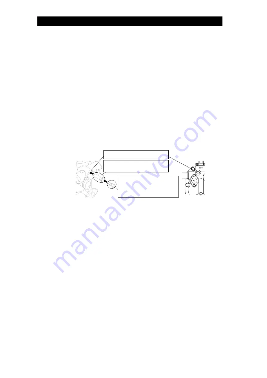
The exhaust pipe/tube [Se] should be connected to the upper part of the
condensate receiver [Dh]. The exhaust pipe/tube [Se] should be shorter than 3 m,
and with an inner diameter of 8 mm or greater.
Do not remove the exhaust plug installed on the product. This exhaust plug is
needed to achieve proper operation. In the event the exhaust plug has been
removed, wrap the thread part with 3
– 3.5 turns of sealing tape or apply sealing
compound and tighten it to a torque of 30 N
・
m (22 lbf
・
ft).
Connect the exhaust pipe/tube to the exhaust plug (inner diameter of 8 mm (
1
/
4
in)).
The pipe/tube can be connected using a commercially-available nipple, street
elbow, ring joint, etc.
When steam or high temperature air is used as a motive medium, make sure to use
the steel pipe for the exhaust pipe/tube [Se].
(6) Inlet and Outlet Piping
Install a condensate inlet pipe [Si] to help condensate flow into the PowerTrap by
gravity. The pipe thickness should be schedule 40 or less for proper operation.
Install a condensate inlet strainer [Ki] (40-mesh or finer) on the PowerTrap pumped
medium inlet pipe and install a union joint for maintenance.
The condensate outlet pipe [So] diameter should be at least 25 mm (1 in).
During pumping operation, the PowerTrap uses the motive medium supply
pressure to push out the condensate from the body. The GP5C can discharge
approximately 1.5 liters (
3
/
8
US Gallons) of pumped medium for each discharge
operation. The amount of time required for each discharge operation will be
between 5 and 30 seconds, depending on the back pressure and the motive
medium pressure.
This means that the instantaneous flow through the pumped medium outlet pipe
during the discharge operation is between 170 kg (370 lb) and 1 metric ton (2200
lb) per hour.
Accordingly, flowmeters must not be installed on the condensate outlet pipe [So].
Install a steam flowmeter at the steam-using equipment inlet if necessary.
(7) Valves on the Various Pipes
In order to ensure the proper discharge capacity, use full bore ball valves or gate
valves on the condensate inlet [Vi] and outlet pipes [Vo].
Be sure to install a blowdown valve [Vb]. A bellows sealed valve is recommended,
due to the lack of leakage from the gland and easy flow rate adjustment.
Install union or flanged joints between the valves and the PowerTrap to allow for
Exhaust Plug
(Already installed to the product)
Use commercially-available
nipples
(inner diameter of 8 mm (
1
/
4
in))
(Not included in the package)
Exhaust Port


