background image

Edition

Manual

Chapter

Page

2008-10-17 Workshop Manual, Stiga Titan 1 General instructions

8

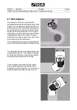
Assembly of seat

Install the seat as follows:
1. Place the seat in place and assemble the 

two front screws with nuts. Don´t tight yet.

2. Assemble the two rear screws with nuts.
3. Tigheten the four screws.

Assembly of headrest

Install the headrest as follows:
1. Hold the headrest in place and assemble 

the two screws . 

2. Tigheten the screws.

x2

Содержание TITAN 20 B

Страница 1: ...Workshop manual Titan 2008 2012 ...

Страница 2: ...chapter Chapter 2 Chassis Chapter 3 Steering Chapter 4 Hydraulic system Chapter 5 Belts Chapter 6 Control Wires Chapter 7 Electrical system 1 3 2 Extended guarantee 4 1 3 3 Component guarantee chassis 4 1 3 4 Exeptions 4 1 3 5 Conditions for validity of the war ranties 4 1 4 Unpacking and assembly 5 1 4 1 Unpacking 5 1 4 2 Battery 6 1 4 3 Assembly 7 1 4 4 Final checks 9 1 5 Service 11 1 6 Technica...

Страница 3: ...on the Accessory Lifter you will find this in chapter 3 Chassis and Body On the first page in chapter 3 there is a detailed table of contents which refers to the correct section in this case section 3 1 Always check that you are reading the right chapter for your particular machine before starting the repair work 1 1 3 Abbreviations The following abbreviation is used in this manual PTO Power Take ...

Страница 4: ...rk under the machine always make sure that lifting devices and jack stands are approved for the weight Work safe 1 2 5 Cleanliness Clean the machine before starting repairs Dirt that penetrates into sensitive components can seriously influence the service life of the machine Special important is the cleanliness when working with the hydraulic system See special warnings in that chapter 1 2 6 Tight...

Страница 5: ...d out at an authorised service workshop during the relevant guarantee period The services must be verified in the service book 1 3 4 Exeptions The extended warranty does not cover damage due to the following Neglect by users to acquaint themselves with accompanying documentation Carelessness Incorrect and non permitted use or assembly The use of non genuine spare parts The use of accessories not s...

Страница 6: ...The pressure is designated adjacent to the actual wheel The air pressure in the tyres is of critical importance for the performance and handling of the machine The correct air pressure for mowing is 0 9 bar in all tyres When using the machine with other implements see the respective implement manual regarding the tyre pressure However the maximum permitted pressure is always 1 3 bar Too high press...

Страница 7: ...f a short circuit and damage to the battery If the cables are interchanged the generator and the battery will be damaged The engine must never be driven with the battery disconnected There is a risk of serious damage to the generator and the electrical system Installation of battery See also the respective installation manual delivered with the machine After the battery is charged remove the motor...

Страница 8: ...Assemble the machine as follows Assembly of steering wheel The machine is delivered without the steering wheel with its rod disassembled Assemble as follows 1 Install the steering column jacket on the steering column 2 Check that the holes coincide 3 Secure by knocking in the tension pin fully Use a counterhold Also make sure that the logo on the steering wheel is in the correct position ...

Страница 9: ...tall the seat as follows 1 Place the seat in place and assemble the two front screws with nuts Don t tight yet 2 Assemble the two rear screws with nuts 3 Tigheten the four screws Assembly of headrest Install the headrest as follows 1 Hold the headrest in place and assemble the two screws 2 Tigheten the screws x2 ...

Страница 10: ...he water separator s and fuel fil ter s taps are open Check that the water separator does not con tain water Drain if necessary Check the oil level in the hydraulic tank See 3 5 8 in instructions of use Carry out safety checks Check that the disengagement lever is in the inner position See 3 4 19 Test driving Drive the machine for a few minutes Test all the functions Pay special attention to the s...

Страница 11: ...ould stop Test driving No unusual vibrations No unusual noise Status Action Result The clutch brake pedal not depressed PTO not activated Attempt to start The engine should not start The clutch brake pedal not depressed PTO activated Attempt to start The engine should not start Engine running PTO activated The operator leaves the seat PTO should dis engage Cruise control activated The operator lea...

Страница 12: ...ccording to the table below regarding items and intervals Service point 1st time Interval See paragraph in instruc tions of use Hours of opera tion Calendar months Water separator check 50 6 4 Pre filter cleaning 6 4 Fuel filter replace 400 6 5 Tyre pressure check adjust 6 6 Engine oil filter change 50 12 200 12 6 7 Hydraulic oil filter change clean 50 12 400 12 6 8 Wheel motors change oil 50 12 2...

Страница 13: ... rpm 14 kW 19 Hp 18 5 kW 25 Hp 18 5 kW 25 Hp 18 5 kW 25 Hp High idle speed 3200 rpm 3200 rpm 3200 rpm 3200 rpm Low idle speed 1250 rpm 1250 rpm 1250 rpm 1250 rpm Bore 70 mm 76 mm 76 mm 76 mm Stroke 74 mm 82 mm 82 mm 82 mm Displacement 854 cc 1115 cc 1115 cc 1115 cc Low temp specification 20 C 20 C 20 C 20 C Low temp starting aid standard standard standard standard Emission standard EU N A US EPA T...

Страница 14: ...c oil type 10W 30 10W 30 10W 30 10W 30 Reduction gear in wheel motors oil type 90 or SAE 50 90 or SAE 50 90 or SAE 50 90 or SAE 50 Power take off PTO PTO type Belt Belt Hydraulic Hydraulic PTO pump 14 cc gear pump 14 cc gear pump PTO pump operating pressure 210 bar 210 bar PTO pump max output 42 l min 42 l min Frame and steering Steering system Genuine articulated steering Genuine articulated stee...

Страница 15: ...d nuts on the machine 1 7 Instructions for use Some procedures e g changing motor oil motor filter and items in final checks etc are refered to the instruction for use delivered with the machine The instruction of use is written in 16 languages and divided in two parts The first part always contains the languages SV FI DA NO DE EN FR and NL Tightening torques Thread Torque M5 5 Nm M6 9 Nm M8 22 Nm...

Страница 16: ...achines are equipped with a various number of aid equipments These equipments can be hydraulic electric or mechanic devices This chapter gives a brief description of the equipments and describes their repair and replacements 2 1 Description 2 2 2 Cruise control 3 2 2 1 Description 3 2 2 2 Disassembly 3 2 2 3 Assembly 4 2 3 Cooler 5 2 3 1 Description 5 2 3 2 Disassembly 5 2 3 3 Assembly 6 2 3 4 Fil...

Страница 17: ...common and a requirement when cutting around trees and corners The rear wheel will never pass a bend in an inner circle and interfere with the obstruction This configuration also gives an optimal small uncut circle when driving with maximal turning The articulated frame is also articulating in the vertical plane with 6 This makes it possible for all the four wheels to press evenly against the grou...

Страница 18: ... against the brake plate B Such the mechanics drive pedal linkage and hydraulic pump lever are locked in position for desired speed 2 2 2 Disassembly Disassemble the speed cruiser as follows 1 Remove the upper and the right motor hoods 2 Disconnect the drive wire from the pump lever by loosening the nut Use a 10 mm spanner To lock the stud in the hole preventing it to rotate press the wire end upw...

Страница 19: ...e brake bracket by unscrewing the two nuts 6 Loosen the drive wire from the brake bracket 2 2 3 Assembly Assemble all parts in reverse order See also the figure If the drive wire has been removed from the brake bracket adjust the wire See 2 4 5 Adjustment Note Check that the megnet tab D fits in the lever hole D ...

Страница 20: ...ows 1 Remove the motor hoods Turn and remove the screws A Unhook the straps B X 4 Lift up and remove the 4 hoods Unscrew the 4 screws C and remove the top hood The coolant is very hot direct after use Let the motor cool down before draining the coolant 2 Place a tray under the lower radiator hose and loosen the hose from the radiator The hose clamp is accessible from the under side 3 Remove the ra...

Страница 21: ...t must meet the following requirements Always use a mixture of refrigerant and water Never use just water Mix the water and refrigerant according to the refrigerant supplier s instructions Never mix different refrigerants Use soft water no calcium content distilled or demineralised water Top up as follows 1 Check that all the plugs in the cooling sys tem are installed and sealed 2 Check that all t...

Страница 22: ...d check the level in the expansion tank The level should now be at the upper mark T which is the level for when the engine is hot 11 If the level is not up to the upper mark allow the engine to cool and then top up with cool ant in the expansion tank 2 4 Lubrication chassis All lubrication points according to the table below must be lubricated after every 50 operating hours as well as after each c...

Страница 23: ... 3 lubrication nipples J Tension arm auxiliaries belt Only 20B and 26B 1 lubrication nipple Be careful with the belts Belts must not come into contact with grease L Tension arm rear implement belt Only 20B and 26B 1 lubrication nipple Be careful with the belts Belts must not come into contact with grease K Throttle cable Lubricate the cable ends using an oil can at the same time as activating the ...

Страница 24: ...Edition Manual Chapter Page 2008 10 23 Workshop Manual Stiga Titan 2 Chassis and body 9 B C D E G H D F J K A ...

Страница 25: ... the front and rear frames into desired angels The hydraulic assisted system gets its power from the pump for external hydraulics integrated to the driving pumps This chapter contains a brief description of the function and describes repair replacements and adjustments of stressed parts of the steering system 3 1 Description 2 3 1 1 Disassembly the steering servo 3 3 1 2 Repair of the steering ser...

Страница 26: ...Edition Manual Chapter Page 2008 10 17 Workshop Manual Stiga Titan 3 Steering 2 3 1 Description The description of the oil flows in the hydraulic assisted steering system is given in section 4 ...

Страница 27: ...ervo 1 Dismantle the steering bracket rear cover by unscrewing the four screws 2 Disassemble the steering wheel by knock ing out the tension pin 3 Dismantle the front cover by unscrewing the four screws 4 Disconnect the cables from the front lights 5 Dismantle the inner front cover by unscrew ing the four screws ...

Страница 28: ...semble the steering servo by unscrew ing the four upper screws A 3 1 2 Repair of the steering servo The only repair which can be actual at the steering servo is changing of the O rings See section 4 3 1 3 Assembly the steering servo 1 Assemble the steering servo in the reverse order Be sure to connect the hydraulic hoses to their desired places marked during the dis assembly The system will be aut...

Страница 29: ...le position The wheel should spring back approx 10 20 mm when the wheel is released after turning However the machine will not automatically drive straight forward after turning in the same way as a car If the machine always turns in the same direc tion as soon as the engine is started there is probably a fault in the torque converter Another conceivable fault can be that the bear ing in the steer...

Страница 30: ...es and protection goggles during works with the hydraulic system Before starting the motor place the machine outdoors or install an extraction device for the exhaust fumes Otherwise the personel will be poisoned Cleanliness is mandatory at all works with the hydraulic system Foreign substances and contaminations will jeopardize the function and reliability of the system Always protect and close op...

Страница 31: ... systems Driving system External hydraulics PTO drive These systems work with the same oil but in separate parallel systems Each system has its own separate hydraulic pump The driving system pressure is depending on the power requirements at the wheel axles and is limited by the engine power The PTO drive system pressure is depending on the power requirements in the implement and is limited to 220...

Страница 32: ...in pump Green lines can act both as pressure lines and return lines depending on the driving direction Blue is the atmospheric pressure in the oil container and housings 1 Wheel motor rear left 2 Wheel motor rear right 3 Wheel motor front left 4 Wheel motor front right 5 Collector block 6 Feeding pump 7 Main pump 8 Main flow line reverse driving 9 Main flow line forward driving 10 Main flow line b...

Страница 33: ...he physical parts of the wheel motors are as follows 1 Hole for lifting eye 2 Hydraulic motor 3 Main ports upper 4 Parking brake lever Only front motors 5 Wheel axle 6 Planetary reduction gear 7 Filling level plug for reduction planetary gear 8 Drain plug plug for reduction planetary gear 9 Drain port hydraulic motor 10 Main ports lower Shoe configuration There are two configurations in contact be...

Страница 34: ...4 Hydraulic system 5 Hydraulic pumps There are three hydraulic pumps built together into one unit Main pump for the driving system 13 Charge pump for the main pump 12 Pump for the external hydraulics 11 This pump belongs not to the driving system See 10 and 15 11 12 13 ...

Страница 35: ...een is the feeding pressure to the main pump Blue is the atmospheric pressure in the oil container and housings 1 Wheel motor rear left 2 Wheel motor rear right 3 Wheel motor front left 4 Wheel motor front right 5 Collector block 6 Feeding pump 7 Main pump 8 Main flow line reverse driving 9 Main flow line forward driving 10 Main flow line between right motors 11 Main flow line between left motors ...

Страница 36: ...ding pressure to the main pump Blue is the atmospheric pressure in the oil container and housings 1 Wheel motor rear left 2 Wheel motor rear right 3 Wheel motor front left 4 Wheel motor front right 5 Collector block 6 Feeding pump 7 Main pump 8 Main flow line reverse driving 9 Main flow line forward driving 10 Main flow line between right motors 11 Main flow line between left motors 12 By pass lin...

Страница 37: ...depending on the power requirements at the wheels and is limited by the engine power Leak oil The wheel motors and the hydraulic pump have a small oil leakage 1 4 which increases with increased power requirement increased pressure The leakage oil is collected inside the unit housings and forwarded to the collector block back to the oil tank through the leak flow lines 17 The charge pump 6 compensa...

Страница 38: ...to disable the resistance in the main pump and allow the oil to circulate in the system when the wheels need to be turned However when the by pass valve is actuated the resistance in the system is still not zero why it is only allowed to push the machine short distances i e up on a trailer 9 Main flow line forward driving 10 Main flow line between right motors 11 Main flow line between left motors...

Страница 39: ...e is the atmospheric pressure in the oil container and lines Green lines can act both as pressure lines and return lines depending on the movements 1 Steering servo including the following A Pressure limiting valve B Chock valves C Steering unit Terminals at the steering servo P Unregulated inlet from the hydraulic pump for external hydraulics T Outlet to the tank for leak oil and oil from the pas...

Страница 40: ...xternal hydraulics never can exceed 125 bar B Chock valves The chock valves are intended to reduce the pressure in the pressure liner 2 and 3 if a sudden obstacle or blocking occours during the driving C Steering unit The steering unit has a built in attribute to always give priority to the steering function in cases when the stering and external hydraulics are used at the same time 4 Steering cyl...

Страница 41: ...t machines also via the cooler 16 6 Pump for external hydraulics integrated to the driving pumps 7 Pressure line 8 Suction line 9 Leak flow line and return line 10 External hydraulics Colour Pressure Red is the feeding pressure to the steering servo and external hydraulics Blue is the atmospheric pressure in the oil container and lines Green lines can act both as pressure lines and return lines de...

Страница 42: ...c pressure in the oil container and lines Green lines can act both as pressure lines and return lines depending on the movements 1 Steering servo including the following A Pressure limiting valve B Chock valves C Steering unit Terminals at the steering servo P Unregulated inlet from the hydraulic pump for external hydraulics T Outlet to the tank for leak oil and oil from the passive side of steeri...

Страница 43: ...c pressure in the oil container and lines Green lines can act both as pressure lines and return lines depending on the movements 1 Steering servo including the following A Pressure limiting valve B Chock valves C Steering unit Terminals at the steering servo P Unregulated inlet from the hydraulic pump for external hydraulics T Outlet to the tank for leak oil and oil from the passive side of steeri...

Страница 44: ...follow the contours of the ground Use the floating position when carrying out work Lowering The implement lowers regardless of its weight The lowering speed can be set using the control 4 The lowering force is determined by the implement s weight and the hydraulic down force that is applied when lowering Locking in the transport position The lever has returned to the neutral position after raising...

Страница 45: ...eturn lines with atmospheric pressure Green lines can act both as pressure lines and return lines depending on the implement movement F Implement lifter cylinder F1 Control lever for the implement lifter F L Hydraulic output front left at B machines and middle at H machines L1 Control lever for the hydraulic output L R Hydraulic outputs front right Re Hydraulic outputs rear R1 Control lever for th...

Страница 46: ...lves F1 and L1 have a small oil return leakage To prevent the implement moving due to its own weight the oil flow is stopped by these valves To facilitate the flow when the implement shall move in this direction the valves are mechanical affected of the valve slide to open 4 Check valve lowering This valve is adjustable and its purpose is to reduce the oil flow and thus adapt the speed to implemen...

Страница 47: ...eturn lines with atmospheric pressure Green lines can act both as pressure lines and return lines depending on the implement movement F1 Control lever for the implement lifter F L1 Control lever for the hydraulic output L R1 Control lever for the hydraulic outputs R and Re T Tank 5 Collector block 6 By pass line Oil flows from the steering unit through the by pass line 6 The oil is then flowing ba...

Страница 48: ... atmospheric pressure Green lines can act both as pressure lines and return lines depending on the implement movement F Implement lifter cylinder F1 Control lever for the implement lifter F T Tank The by pass line is blocked in valve F1 Oil flows from the steering unit through the valve F1 The valves 2 and 4 become fully open The piston in cylinder F is pressed against its bottom and the lifter ri...

Страница 49: ...is pressed back to the tank via the the valves 4 2and F1 and the collector block The valve 2 is mechanic opened by mechanic connection with the slide in F1 and valve 4 is adjusted to desired lowering speed movement F Implement lifter cylinder F1 Control lever for the implement lifter F T Tank 1 Pressure limiting valve 2 Mechanic actuated non return valve 4 Check valve lowering 5 Collector block Co...

Страница 50: ...fting cylinder F The valve 2 is mechanic fully opened by mechanic connection with the slide in F1 and valve 4 is also opened for desired speed at lowering The limited opening area in valve 4 has no affect to the low oil flow at the floating F Implement lifter cylinder F1 Control lever for the implement lifter F T Tank 2 Mechanic actuated non return valve 4 Check valve lowering 6 By pass line Colou...

Страница 51: ...re Green lines can act both as pressure lines and return lines depending on the implement movement L Hydraulic output front left at B machines and middle at H machines L1 Control lever for the hydraulic output L T Tank The by pass line is blocked in valve L1 Oil flows from the steering unit through the valve L1 output L through the implement performing the movement Thereafter back to the output th...

Страница 52: ...pressure Green lines can act both as pressure lines and return lines depending on the implement movement L Hydraulic output front left at B machines and middle at H machines L1 Control lever for the hydraulic output L T Tank The by pass line is blocked in valve L1 Oil flows from the steering unit through the valve L1 valve 3 output L and to the implement performing the movement Thereafter back to ...

Страница 53: ...ending on the implement movement R Hydraulic outputs front right Re Hydraulic outputs rear R1 Control lever for the hydraulic outputs R and Re T Tank The by pass line is blocked in valve R1 Oil flows from the steering unit through the valve R1 the outputs R Re and to the implement performing the movement Thereafter back to the output through the valve R1 collector block 5 and back to the tank The ...

Страница 54: ...ending on the implement movement R Hydraulic outputs front right Re Hydraulic outputs rear R1 Control lever for the hydraulic outputs R and Re T Tank The by pass line is blocked in valve R1 Oil flows from the steering unit through the valve R1 the outputs R Re and to the implement performing the movement Thereafter back to the output through the valve R1 collector block 5 and back to the tank The ...

Страница 55: ...pressure lines to the implement Blue is the return lines with atmospheric pressure See also next page regarding locations on the machine and further descriptions of the components 1 PTO valve including items 2 3 4 and 6 below 2 Electrical solenoid 3 Slide including a left and a right valve 4 Pressure limiting valve 125 bar 5 Collector block 6 Brake valve 7 Cooler 8 Leak oil line P Hydraulic pump P...

Страница 56: ... line never can exceed 125 bar i e if the rotating parts are blocked 6 Brake valve The brake valve minimizes the stop time for the implement 7 Cooler As the motor is started the PTO oil passes through the cooler Since the same oil is used for the driving the cooler keeps the hydraulic oil on a suitable level 8 Leak oil line The leak oil line transports all leak oil from the implement hydraulic mot...

Страница 57: ... left valve and returns to the tank via the cooler Only a slight pressure occours in the lines depending on the line and valve resistance 1 PTO valve including items 2 3 4 and 6 below 2 Electrical solenoid 3 Slide including a left and a right valve 4 Pressure limiting valve 220 bar 5 Collector block 6 Brake valve 7 Cooler 8 Leak oil line P Hydraulic pump PTO Hydraulic outputs PTO1 Switch T Tank Co...

Страница 58: ...rns to the tank via the cooler If an abnormal resistance occours in the pressure line i e blocked motor or similar the pressure limiting valve 4 will open at 220 bar adjustable and the oil returns to the tank via this valve 1 PTO valve including items 2 3 4 and 6 below 2 Electrical solenoid 3 Slide including a left and a right valve 4 Pressure limiting valve 220 bar 5 Collector block 6 Brake valve...

Страница 59: ...ake valve are working together The right valve closes and the oil is forced through the brake valve which ensure a pressure of 10 bar adjustable This will consume the energy from the tools which will stop smooth and fast From the brake valve the oil returns to the tank via the cooler 1 PTO valve including items 2 3 4 and 6 below 2 Electrical solenoid 3 Slide including a left and a right valve 4 Pr...

Страница 60: ...aminated change oil if neccesary Symptom Fault Measure The machine drives forwards but not backwards Big leakage in one of the front motors Replace the actual motor The machine drives backwards but not forwards Big leakage in one of the rear motors Replace the actual motor Reduced or no speed The belts between motor and pump are slipping Check if the pump pulley rotates Replace the belts Big leaka...

Страница 61: ...e set cutting height drops Faulty non return valve 3 Hoses mixed up at the deck The cutting height cylinder is leaking See the next two pages Sped control for lowering from transport position works not The check valve for lowering is faulty connected See page 34 Implement function connected to the hydraulic output L1 is unintended lowering returning Faulty the non return valve 3 Replace the non re...

Страница 62: ...k hoses are correct connected See Repair Control hydraulics in the Mower deck manual Change hose positions at the faulty unit machine or deck 1 Lift the implement to transport position 2 Fully close the check valve for lowering 3 Move the control lever F1 for the implement lifter fully forwards to the float position The front mounted implement is not staying in transport position Wait 3 hours Does...

Страница 63: ...on 2 Close the check valve completely by turning it clockwise 3 Put the lever F1 forward to float position and the implementer shall stay in raised position 4 It the implement drops perform the solution below Solution Open the control panel and loosen the check valve Turn it 180 and fit it again See the figure After repair perform the test above again 2 3 4 ...

Страница 64: ... drain plug C remove the plug and let the oil run out into a container The container must have a capac ity of 20 litres 4 Dispose of the oil according to local regula tions 5 Install the oil drain plug Tighten to 40 Nm 6 Fill with new oil through the filter opening at the top Oil See Section 1 Oil quantity when changing See Section 1 7 Reinstall the filter with the following compo nents D Cover G ...

Страница 65: ...and damage to the hydraulic system 4 7 3 Disassembly the hydraulic pumps Disassembly the hydraulic pumps as follows 1 Drain the hydraulic oil See above 2 Dismantle the cruise control device fitted to the hydraulic pumps See section 2 3 Remove the hydraulic pump belts See sec tion 5 4 Remove the pump pulley by holding it with a big polygrip or similar while loosening the axle nut Use a 19 mm spanne...

Страница 66: ...se front motor B Drive hose rear motor C Drive hose rear motor D Drive hose front motor E External hydraulik tank hose F External hydraulic hose 8 Loosen and remove the two pump attach ment screws and move the pump carefully outwards The leak oil hose is still connected to the pump inside 9 Loosen and disconnect the leak oil hose and take out the pump 10 Disassemble all connections from the pump a...

Страница 67: ...isconnet the hydraulic hoses from the pump 3 Dismantle the pump together with its carrier plate pulley See 5 4 Hydraulic pumps belts 26H 26HS in section 5 Note the stabilisation spring It shall also be unhooked 4 Take out the pump from the machine and set up the pulley in a vise 5 Unscrew the pulley nut and remove the pulley from the shaft If neccesary use a puller The shaft fitting is conical ...

Страница 68: ...low 5 Disassemble the 5 connections A 6 Lift carefully up the following parts and place them on the clean surface C Connection plate D Distance shaft E Impeller F Impeller shaft H Pump body J Flow disc Note Be sure to keep the body entirely verti cal when removing the valve shaft K If not the locking pin L can move and lock the unit inside the body K Valve shaft Do not remove the locking pin L Sec...

Страница 69: ...emble all parts in the reverse order Replace all O rings 3xG 5xB with new one during the assembly Remark the following important advises dur ing the assembly Apply som motor oil on the sealing ring surfaces Check that the locking pin in the valve shaft not protrude during the insertion If not there is a risk of locking in the body groves The damper rod shall be fitted in hole P See the relation to...

Страница 70: ...g cylinder and for the lifting cylinder Disassembly 1 Disassemble the actual hydraul cylinder from the machine See section 3 2 Clean thoroughly the steering servo A B C D E F G H J K L M B C E 3 Prepare a clean surface on the work ing bench and cover with a clean paper or similar No contaminants must enter the hydraulic system This causes serious damage to components of the systems ...

Страница 71: ...ngs in the actual places Replacing the link bearing M If the link bearings shall be replaced take out the locking ring L and press out the bearing Assembly of the hydraul cylinder 1 Set preferably up the hydraul cylinder in a vise No contaminants must enter the hydraulic system This causes serious damage to components of the systems 2 Assemble all parts in the reverse order Remark the following im...

Страница 72: ...ax pressure 4 MP measure terminal for the brake pressure Adjustment of max pressure 1 Connect a manometer to measure terminal MT1 2 Start the motor and activate the PTO without any implement connected 3 Adjust the pressure with valve 3 and read the pressure at the manometer Adjustment of brake pressure 1 Connect a manometer to measure terminal MP 2 Start the motor and activate the PTO with an impl...

Страница 73: ...placement procedures of belts clutch and bearings There are no adjustment procedures involved in this system All adjustments are performed automatic with spring loaded tension arms 5 4 Hydraulic pumps belts 26H 26HS 8 5 4 1 Description 8 5 4 2 Disassembly 8 5 4 3 Inspections 10 5 4 4 Assembly 10 5 5 PTO pulley with bearing 20B 26B 11 5 5 1 Description 11 5 5 2 Disassembly 11 5 5 3 Assembly 12 5 1 ...

Страница 74: ...ntended to display the importance to use the original belts Case Commercial grade belts Original spare parts belts Remarks Fitness to pulleys The belt shall rest with its angled sides against the pulleys There must be a space between belt and pulley bottom The belt shall rest with its angled sides against the pulleys There must be a space between belt and pulley bottom Same demands Original belts ...

Страница 75: ...ber Bending in two directions Designed to bend around pulleys in one direction only Most of the belts at the machine have tension rollers actuating from the outside of the belt This means the the belt has to bend both inwards and outwards during the operation All original belts which operate with tension rollers actuating from the outside have reinforcements The reinforcement is special designed f...

Страница 76: ...gnetic clutch PTO clutch The belt is angeled over two pulleys of which one is the tensioning pulley fitted to a spring loaded lever Such the belt is automatic tensioned 5 2 2 Disassembly Dismantle the PTO belt as follows 1 Dismantle all eventual implements from the machine See the respective instructions 2 Remove the rear motor hood C Turn and remove the screws A Unhook the straps B Lift up and re...

Страница 77: ...he clutch cables G 6 Turn the clutch somewhat to the left and take out the belt 5 2 3 Inspections Check the belt according to 2 Belt theory Check the pulley bearings All defective parts shall be replaced Item Check instruction Bearing noise Rotate the pulley and listen for abnormal noise and feel if any uneven resistance exists If any abnormal noise is heard or if any uneven resistance exists shal...

Страница 78: ...ne oil 2 Fit the belt to all pulleys without the tension pulley 3 Fit the spring H to its eyebolt and hole in the lever 4 Force the lever D backwards until pulley E have risen enough and apply the belt to the pulley 5 Assemble the remaining parts 5 3 Hydraulic pumps belts 20B 26B 5 3 1 Description The hydraulic pumps belts consist of two parallel belts which transmit the motor power to the driving...

Страница 79: ...en the belts Warning Be carefully not to slip with the screw driver Risk for hand injuries 4 Work off the belts from the tensioning pulleys while forcing the screwdriver downwards 5 Work off the belts from the pump pulleys 6 Remove the belts 5 3 3 Inspections Check the belt according to 2 Belt theory 5 3 4 Assembly Assemble all parts in the reverse order Note The belts are delivered in a set of tw...

Страница 80: ...rallel belts which transmit the motor power to the driving system and external hydraulics pumps The belts are automaic tensioned by a spring loaded lever with tensioning pulleys 5 4 2 Disassembly Dismantle the hydraulic pumps belts as follows 1 Remove the rear motor hood C Turn and remove the screws A Unhook the straps B Lift up and remove the hood C 2 Remove the right motor hood D x2 A B A B C D ...

Страница 81: ...ng Be carefully not to slip with the screw driver Risk for hand injuries 4 Work off the belts from the tensioning pulleys while forcing the screwdriver downwards 5 Unscrew the nut from the screw and remove the following parts located under the pump Nut G Distance F Screw E Use two 17 mm keys 6 Unscrew the two upper screws and loosen the hose clamp and remove the air cleaner G F E ...

Страница 82: ... three screws halv way in a first step Thereafter turn the flywheel once again and remove the screws 8 Pull out the pump with the carrier plate pulley Work off the belts and thread them between the carier plate and the flywheel 5 4 3 Inspections Check the belt according to 2 Belt theory 5 4 4 Assembly Assemble all parts in the reverse order Note The belts are delivered in a set of two belts which ...

Страница 83: ... 20B 26B 5 5 1 Description The PTO pulley is driven on its upper track via a belt from the motor The PTO is performed from the lower track 5 5 2 Disassembly Dismantle the PTO pulley as follows 1 Disassembly the PTO belt See 4 PTO belt 20B 26B 2 Unscrew the screw and take out the pulley assy Use a 17 mm key 3 Disassemble the shaft ...

Страница 84: ... ring It will destroy the bearing before it is even used If new bearings shall be assembled use a press and press only against the bearing outer ring Don t forget the bearing distance D Item Check instruction Bearing noise Rotate the the bearing and listen for abnormal noise and feel if any uneven resistance exists If any abnormal noise is heard or if any uneven resistance exists shall the bearing...

Страница 85: ... movements from the operator to the respective device on the ma chine are conducted by wires This chapter gives a brief description of the equipments and describes their repair and re placements 6 3 Brake wires 6 6 3 1 Description 6 6 3 2 Disassembly 6 6 3 3 Inspections 7 6 3 4 Assembly 7 6 3 5 Adjustment 8 6 4 Throttle wire 8 6 4 1 Description 8 6 4 2 Disassembly 9 6 4 3 Assembly 10 6 4 4 Adjustm...

Страница 86: ... from the actual lever For wire adjustment purpose The wire ten sion is adjusted by screwing the link on off the threaded rod at the wire Note At the adjustment at least 5 threads shall be engaged To change a elbow link 1 Loosen the nut 3 with a 8 mm wrench 2 Remove the nut 1 with a 8 mm wrench Hold the elbow stud with a 7 mm wrench 3 Screw the elbow link off the rod 4 The assembly is performed in...

Страница 87: ... both holes in the elbow link body otherwise the link will separate during operation Adjustment 1 Loosen the nut 3 with a 8 mm wrench 2 Apart the elbow link as described above 3 Screw the link body in the desired direction on the wire stud If neseccary move the nut 3 on the stud 4 Check the adjustment result by pressing on the elbow link onto the sphere and without assembling the circlip 5 After a...

Страница 88: ...he wire is moving easily in its conduit The wire transmitts both pulling and pushing forces 6 2 2 Disassembly 1 Loosen the wire and its conduit at the hydraulic pump See 2 3 Cruise control 2 Remove the floor mat and dismantle the front floor by unscrewing its four screws 3 Loosen the wire and its conduit at the front end 3 Loosen all attachment straps and remove the wire from the machine Observe h...

Страница 89: ...ire between its end positions until the oil has reached the entire wire 2 Fit the wire to the machine as observed dur ing the disassembly See also the figure 3 Adjust the wire See below 6 2 5 Adjustment It is important that the drive wire is correct adjusted otherwise the max backward forward positions can not be reached and the wire is exposed for excessive stress Adjust the wire as follows 1 Rem...

Страница 90: ...ion No furthet play on the pump lever when the drive pedal is in its max posi tions 7 Refit the motor hoods 6 3 Brake wires 6 3 1 Description The brake wires are transmitting the movement from the brake pedal lever to the front wheel motors brake lever Since the brakes belong to the machine safety system It is of great importance that the brake wires are faultless and correct adjusted Warning Neve...

Страница 91: ...ck that the wire can be easily moved in its conduit during the entire stroke Check that the conduit is free from sharp bends and other damages The conduit outer cover must be intact to prevent water to enter the wire Check that the conduit end sealings are intact 6 3 4 Assembly 1 Lubricate the wire through its end sealings Use machine oil Slide the wire between its end positions until the oil has ...

Страница 92: ... follows 1 Measure the spring length at not actuated brakes The length shall be 56 mm 2 Actuate and lock the brake 3 Now the spring length shall be 60 mm 4 Adjust both wires at their adjustment sleeves until the measurement above is ful filled Note The wires can be adjusted in their both ends 5 Lock the adjustment sleeves with their lock nuts after the adjustment 6 4 Throttle wire 6 4 1 Descriptio...

Страница 93: ... Disassemble the three lever knobs by unscrewing them and simultaneously pull them upwards 2 Remove the control panel casings by unscrewing the 11 screws in the figure 3 Disassemble the lever knob by unscrewing it and simultaneously pull it upwards 4 Disassemble the four attachment screws with their nuts ...

Страница 94: ...sassembly See also the figure 2 Assemble remaining parts in the reverse order 3 Adjust the wire See below 6 4 4 Adjustment It is important that the lever can set the pump lever in its end positions Adjust the wire as fol lows Set the throttle lever in full throttle position In this position it shall not be possible to move the pump lever further Set the throttle lever in idle position In this posi...

Страница 95: ...1 Description 2 7 2 Trouble Shooting 3 7 2 1 The starter does not rotate 4 7 2 2 The starter rotate but the motor do not start 5 7 2 3 The battery runs repeatedly empty 6 7 2 4 The motor does not stop 6 7 2 5 The speed cruiser does not work 7 7 2 6 The PTO does not work 8 7 2 7 The electrical cutting height adjustment does not work 9 7 2 8 The sand spreader does not work 9 7 2 9 The electrical rea...

Страница 96: ...efore actual levers and pedals are provided with micro switches The micro switches are shown in the figure below The signals from the micro switches are used to interlock the actual circuit in case of a forbidden manoeuvre attempt Some manual switches and relays have also built in interlocks related to the safety system The wiring diagrams are presented separately in the respective spare parts man...

Страница 97: ...ble shooting schedules it is provided that the following states are fulfilled All fuses are checked and if necessary replaced The battery shall be charged The requirements for the actual measure shall be fulfilled E g if it is advised to perform a start attempt the operator shall sit down on the seat and press the brake pedal When following the trouble shooting shedules it is in normal cases assum...

Страница 98: ... V at terminal B violet cable at the safety relay Is it 12 V between the orange and white cable at the pedal switch Connect temporarily a cable between terminal G yellow cable at the safety relay and earth Does the starter rotate Replace adjust the pedal switch Replace the safety relay 1 Replace adjust the seat switch 2 Replace the PTO relay Clean the connector socket A pos A3 Replace adjust the p...

Страница 99: ... V at the front part of the connector socket B6 when ignition is activated 1 Replace the timer 2 Replace the timer relay 3 Replace the diode Replace adjust the pedal switch Clean the connector socket A pos A5 Is it 12 V at the red cable terminal H at the fuse box Perform actual measure No Yes Yes Yes Are other electrical functions OK when ignition is activated No Yes Is it 12 V during 1 sec at the...

Страница 100: ...ted Is it 12 V at terminal IG at the alternator when the ignition is activated Replace repair the alternator Clean the connector socket A pos A6 No Yes Connect a voltmeter to the battery poles Increases the voltage about 1 3 V when motor is started Replace the battery No Yes No Are all other electrical equipments turned off when the ignition is turned off Replace the ignition switch No Replace the...

Страница 101: ... 12 V between C4 white cable and C5 grey cable in the front part of connector socket C when the speed cruiser is activated 1 Replace the switch at the control panel 2 Replace the speed cruiser relay Clean the connector socket C C4 and C5 No Replace adjust the pedal switch Replace the speed cruiser magnet No Yes No Is it 12 V between C4 white cable and C5 grey cable in the rear part of connector so...

Страница 102: ...nt part of connector socket C when the PTO is activated 1 Replace the switch at the control panel 2 Replace the PTO relay Clean the connector socket C C6 and C7 No Replace adjust the pedal switch Replace the PTO clutch No Yes No Is it 12 V between C7 violet cable and C6 brown cable in the rear part of connector socket C when the PTO is activated Yes Yes Connect a voltmeter to terminal 1 and 3 at t...

Страница 103: ...2 V with alternating polarity when the switch is activated between its positions Replace the cutting height motor Replace repair the cable and cutting heiht contact At the sand spreader contact rear Connect a voltmeter to 31 earth and 54 orange AND between 31 earth and 58 black Activate the switch between its positions Does the voltmeter display 12 V in both measurements No Yes Repair the sand spr...

Страница 104: ... V with alternating polarity when the switch is activated between its positions Replace the switch at the control panel No Yes Repair the implement Clean the connector sockets C C2 and C3 Is it 12 V with alternating polarity between C2 black cable and C3 grey cable in the front part of connector socket C when the height adjustment is activated Yes No Can the motor be started without the brake peda...

Страница 105: ... main electrical components are accessible under the two casings at the control panel Get access to the electrical components as follows 1 Disassemble the three lever knobs by unscrewing them and simultaneously pull them upwards 2 Remove the casings by unscrewing the 11 screws in the figure Relay locations The relays are located as follows A PTO relay and speed cruiser relay at the rear side of th...

Страница 106: ...ector and pull the connector from the switch See the figure Some connectors have 2 pigs 3 Press the fixation tongues on both sides of the switch against the switch Use a screwdriver or similar and work up the switch See the figure 7 3 3 Replacement of switch knob To replace the switch knob there is a special tool available Regarding reference number see the spare parts list Remove the knob by push...

Страница 107: ...o remove the connectors from the plastic holder put a small screwdriver behind the connector hold the cable and pull out the connector See the figure Tab connectors To restore tab connectors if bad crimp forces occur e g after a long time of use the connector can be pinched by a pliers See the figure Screw connectors When cables shall be connected into screw connectors the cable shall be stripped ...

Страница 108: ... aparted 15 from each other Replace the bulbs as follows 1 Dismantle the front cover by unscrewing the four screws 2 Replace the respective bulb by losening the two screws and disconnect the socket 3 Reassemble the parts in the reverse order Note Avoid to touch the bulb front with bare fingers This will decrease the light intensity and shorten the bulb duration ...

Отзывы: