background image

122

122

NV10P - Manual - 01 - 2015

SETTING AND COMMISSIONING

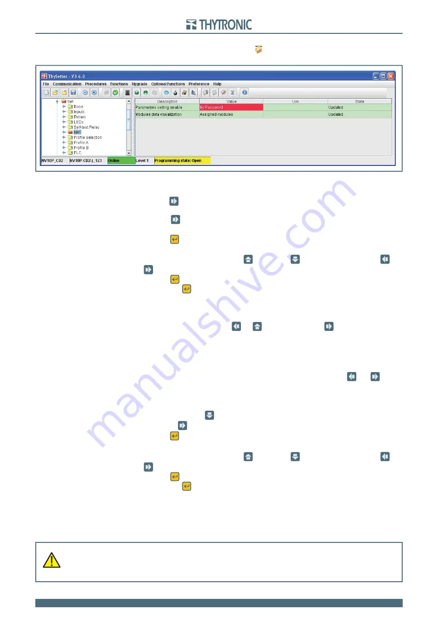
To modify any parameter the calibration session must be open by means of 

Start setting

 command 

from the menu or directly by clicking on the 

 icon placed on the top bar, the opening of the session 

setting is highlighted by its 

Programming state:Open

 on yellow fi eld on the bottom bar.

Operation with Password

If the 

By password

 mode is selected a new menu 

password

 is inserted at the top of the display 

menu.

Press the 

 key the: 

password not ok


>>

 message is displayed and any changes of pa-

rameters is disabled

Press the 

 key; you can enter the password page 

enter password

 where you are 

prompted to enter the 4 characters password (the default password is 0000)

Press the 

 (Enter) button for a few seconds; the modifi cation in progress status is highlighted by 

fl ashing  of the START and TRIP LEDs and by appearance of the pointer on the bottom

Change the parameters by means the 

 (increment) or 

 (decrement) buttons, using the 

  and 

 keys to move to the previous or next character

Press the 

 (Enter) button;  the cursor and the LED TRIP turn off (the LED START keeps fl ashing),

Press the 

  (Enter) button for a few seconds;  new message appears: 

Confirm settings?

Answer to the message  

ENTER: YES

 to confi rm changes or 

RESET: NO

 to abort. 

The message: 

password ok


>> 

is displayed

To exit from password menu use 

  or  

 keys:  if you press the  

 button you go back in the 

password menu and the password must be entered. The parameter changes are enabled from the 
keyboard. After any confi rming with (Enter) or abandoning the change (reset button) the password 
must be entered again.
The possibility of modifying the parameters from the keyboard is automatically disabled after about 
3 minutes elapsed without pressing any button. If you do not want to wait three minutes of waiting, 

it must go back to the password menu and come out without input any data ( 

  and 

 until the 

the message 

password not ok


>> 

is displayed.

Changing the password

Changing the password is possible only after entering the correct password (

password ok


>> 

message); press the 

 key, a new menu is displayed  

change password

 that you ac-

cess with the  

 key. Inside this menu the password can be changed.

Press the 

 (Enter) button for a few seconds; the modifi cation in progress status is highlighted by 

fl ashing  of the START and TRIP LEDs and by appearance of the pointer on the bottom

Change the parameters by means the 

 (increment) or 

 (decrement) buttons, using the 

  and 

 keys to move to the previous or next character

Press the 

 (Enter) button;  the cursor and the LED TRIP turn off (the LED START keeps fl ashing),

Press the 

  (Enter) button for a few seconds;  new message appears: 

Confirm settings?

Answer to the message  

ENTER: YES

 to confi rm changes or 

RESET: NO

 to abort. 

Lost password

If password is lost the data base of the device must be restored, proceed with the following steps:

Activate the session level 1
Send 

Set default settings

 command available inside the 

Command \ Default settings 

menu.

Following the 

Set default settings

 command the password is reset to 

0000

.


WARNING

The command Set default settings restores the factory settings, all user- defined adjustments are cleared.
Be carefully to enter the correct parameter !
The device serial number should be set to avoid IP address conflicts for devices connected to the
Ethernet network.

WARNING

The command Set default settings restores the factory settings, all user- defined adjustments are cleared.
Be carefully to enter the correct parameter !
The device serial number should be set to avoid IP address conflicts for devices connected to the
Ethernet network.

Содержание NV10P

Страница 1: ...NV10P Manual 01 2015 MANUAL NV10P MULTIFUNCTION VOLTAGE AND FREQUENCY PROTECTION RELAY This document applies to NV10P devices with rmware release 3 20 and following...

Страница 2: ...GENERAL SETTINGS FOR INDUCTIVE VTs VERSIONS 16 3 6 1 GENERAL SETTINGS FOR SENSOR VERSIONS 16 3 7 PROTECTIVE FUNCTIONS 16 Thermal protection with Pt100 probes 26 16 Undervoltage 27 for inductive VTs ve...

Страница 3: ...ection with RTD thermometric probes 26 50 Undervoltage 27 52 Positive sequence undervoltage 27V1 56 Overvoltage 59 58 Average overvoltage 59avg 62 Residual overvoltage 59N 64 Negative sequence overvol...

Страница 4: ...hanges via keyboard Password 121 7 3 MENU TREE 123 7 4 MODULES MANAGEMENT 127 7 5 MAINTENANCE 127 7 6 REPAIR 127 7 7 PACKAGING 127 8 APPENDIX 128 8 1 APPENDIX A1 I O Diagram 128 8 2 APPENDIX A2 Interf...

Страница 5: ...endations The warming contained in this document are all important for safety special attention must be paid to the following symbols Installation and commissioning must be carried out by quali ed per...

Страница 6: ...ge ANSI code 59 Overvoltage ANSI code 59N Residual voltage ANSI code 81O Overfrequency ANSI code 81U Underfrequency ANSI code 81R Frequency rate of change ANSI code BF Breaker Failure 74VT VT monitori...

Страница 7: ...value in well speci ed con ditions The dropout ratio may be lower or greater than 1 according as an over or under element is considered Reset time Duration of the time interval between the instant wh...

Страница 8: ...to the 2nd threshold of the 59 element It is not available for reading missing arrow AND and NAND logic gates OR and NOR logic gates Limit block U threshold Computation block Max phase voltage Thresh...

Страница 9: ...F tOFF Minimum pulse width operation for output relays tTR tTR t tTR INPUT OUTPUT tTR 0 T tTR t tTR INPUT OUTPUT Latched operating mode for output relays and LEDs Pulse operating mode for output relay...

Страница 10: ...ed According to the hardware con gurations the NV10P protection relay can be shipped in various case styles depending on the required mounting options Flush Projecting mounting Rack With separate oper...

Страница 11: ...a switching type voltage stabilizing circuit having a very wide working range and a very small power dissipation Nominal frequency 50 or 60 Hz The most signi cant operating features are Programming o...

Страница 12: ...11 Voltage dips short interruptions and voltage variations on dc input power port immunity tests Interruption UT 40 100 ms Interruption UT 0 50 ms Voltage variations UT 80 120 10 s EMC tests for inter...

Страница 13: ...mped oscillatory wave 1 MHz 30 A m Emission Reference standards EN 60255 25 IEC 60255 25 EN 61000 6 4 IEC 61000 6 4 EN 55011 CISPR 11 Electromagnetic emission tests Conducted emission auxiliary power...

Страница 14: ...R Rated consumption for any phase 0 5 VA Residual voltage input circuit Relay residual nominal voltage UEn 50 130 V Permanent overload 130 V Thermal overload 1 s 200 V Rated consumption 0 5 VA Binary...

Страница 15: ...Baud rate 19200 bps Parity None Protocol Modbus RTU Remote ports RS485 Connection screw terminals Baud rate 1200 57600 bps Protocol ModBus RTU IEC 60870 5 103 DNP3 Ethernet 100BaseT Connection Optica...

Страница 16: ...8 Th 1 8 0 200 C Operating time ThAL1 8 tTh 1 8 0 100 s Undervoltage 27 for inductive VTs versions Common con guration 27 Operating logic Logic27 AND OR U Element U Curve type U Curve DEFINITE INVERSE...

Страница 17: ...s Pickup time 0 04 s Dropout ratio 1 03 1 05 Dropout time 0 04 s Overshoot time 0 03 s Pickup accuracy 1 1 Un En Operate time accuracy 5 or 10 ms Positive sequence undervoltage 27V1 for inductive VTs...

Страница 18: ...pe59 Uph ph Uph n 59 Operating logic Logic59 AND OR U Element U Curve type U Curve DEFINITE INVERSE 2 De nite time 59 First threshold de nite time U def 0 50 1 50 Un En step0 01Un En U def Operating t...

Страница 19: ...p 0 1 s Inverse time 59N First threshold inverse time UE inv 0 01 0 50 UEn step 0 01 UEn UE inv Operating time tUE inv 0 10 100 0 s 0 10 9 99 s step 0 01 s 10 0 100 0 s step 0 1 s Element UE UE Reset...

Страница 20: ...e tcUE def 0 07 10 00 s step 0 01 s tcUE Activation time tatcUE 1 60 s step 1 s Pickup time 0 04 s Dropout ratio 0 95 0 98 Dropout time 0 04 s Overshoot time 0 03 s Pickup accuracy 1 1 UEn Operate tim...

Страница 21: ...g time tf def 0 05 100 0 s 0 05 9 99 s step 0 01 s 10 0 100 0 s step 0 1 s f Element De nite time 81U Fourth threshold de nite time f def 0 800 1 000 fn step 0 001 fn f def Operating time tf def 0 05...

Страница 22: ...t df Operating mode Mode df Module Positive Negative De nite time 81R Third threshold de nite time df def 0 1 10 0 Hz s step 0 1 Hz s df def Operating time tdf def 0 00 100 0 s 0 00 0 99 s step 0 01 s...

Страница 23: ...IN27 IN42 with two MID16 modules Delayed binary inputs 7 IN1 IN2 on board IN8 IN10 with MRI module IN11 IN26 with one MID16 module IN27 IN42 with two MID16 modules Start all elements Start U Start U...

Страница 24: ...fundamental component of the input voltages UL1 UL2 UL3 RMS value of fundamental component of the residual voltage UE Calculated Calculated phase to phase voltages U12 U23 U31 Calculated residual curr...

Страница 25: ...RTC EEprom Flash SRam SRam CPU ETHERNET CPU BOARD POWER SUPPLY BOARD DSP DUAL PORT EEprom Thybus RS485 RELAYS K1 K6 Output contacts RS232 MMI LCD LEDs BINARY INPUTS IN1 Input IN2 POWER SUPPLY 5 V 10 V...

Страница 26: ...m which allows the attainment of information pertaining to polarity and amplitude with high resolution The measurement criterion allows precise measurement of even those signals having a unidirectiona...

Страница 27: ...l BP Task The task process e thread are the base components Example are Keyboard management RTC Real Time Clock updating RAM EEPROM updating Diagnostic Input acquisition Output relay management MMI I...

Страница 28: ...c Protocol BP manages the service communication between the kernel and the other modules through the communication buses with the following services Data and information exchange Calibration Upgrade f...

Страница 29: ...U12 U23 U31 and the residual voltage UEC are calculated Signal processing Various processing levels are involved Acquisition base level Direct measures of physical channels rst level Calculated measur...

Страница 30: ...3 UL3 UL1 UL2 UL3 fUL2 T Hz fUL1 T Hz fUL3 T F ai Hz uL1 uL2 UL1 UL2 ACQUISITION VT uL3 UL3 UL1 UL2 UL3 fUL2 T Hz fUL1 T Hz fUL3 T UL1 en ai ACQUISITION uL1 uL2 uL3 DFT TV UL1 UL2 UL3 En UL1 en ai ACQ...

Страница 31: ...trend with square law as shown in the following gure Conventions Phase rotation direction The conventional rotation direction for the voltage phasors is counter clockwise Cyclic phase sequence order F...

Страница 32: ...sequence overvoltage 59V2 g Residual overvoltage 59N g g g g g g g Average voltage 59Uavg Underfrequency 81U g g g g g g Overfrequency 81O g g g g g g Frequency rate of change 81R g g g g g g Breaker...

Страница 33: ...uired if the input is permanently high for a time interval longer than the tOFF setting delay In the above shown diagram INTERNAL STATE represents the logical state of the binary input used in the fol...

Страница 34: ...ff LED relay Reset LEDs Binary input allocation for reset signalling LEDs T 0 INx tON T 0 n o n c INx tON Logic INx tOFF INx tOFF Binary input INx x 1 2 Switch pro le ai A B from binary input OFF Pro...

Страница 35: ...the total counters is practicable by means ThySetter command with Session Level 1 available with password Block1 ai xxxx Block1 Enable ON Enable Block1 input ON Block Block1 Block1 Block1 Binary inpu...

Страница 36: ...Open CB IN IN Binary input IN1 T 0 IN1 tON T 0 n o n c IN1 tON Logic Close CB IN1 tOFF IN1 tOFF Binary input IN2 T 0 IN2 tON T 0 n o n c IN2 tON Logic IN2 tOFF IN2 tOFF Binary input allocation for CB...

Страница 37: ...l a reset command is issued RESET key ThySetter or communication command When pulse operating mode is set Operation MODE Pulse the output relay reset after a tTR programmable delay regardless of the t...

Страница 38: ...relays f ST K g g g g g g f Trip relays f TR K g g g g g g f Trip relays f ST K g g g g g g f Trip relays f TR K g g g g g g f Start relays f ST K g g g g g g f Trip relays f TR K g g g g g g f Start...

Страница 39: ...rip condition Latched the LED doesn t reset at the end of the trip condition it stays ON until a manual reset com mand is issued RESET key ThySetter or communication command Any change to the settings...

Страница 40: ...g g g g g g f Trip LEDs f TR L g g g g g g g f Start LEDs f ST L g g g g g g g f Trip LEDs f TR L g g g g g g g f Start LEDs f ST L g g g g g g g f Trip LEDs f TR L g g g g g g g f Start LEDs f ST L g...

Страница 41: ...is is a con nection oriented transaction which means every query expects a response This query response technique ts well with the master slave nature of ModBus adding to the de terministic advantage...

Страница 42: ...voltage are available UR 100 V and UR 400V The Un relay nominal voltage must be set to the value of relay input voltages at grid nominal volt age The Un value must calculated as If VTs with primary n...

Страница 43: ...connection Es2 Un ai KTV V V 6000 3 100 3 60 Ung 6 0 kV NV10P UL1 UL2 UL3 VOLTAGE INPUTS n a N A L1 L2 L3 B5 B6 B3 B4 B1 B2 Phase to phase VTs connection Es3 Un ai KTV V V 6000 100 60 Ung 6 0 kV NV10P...

Страница 44: ...ge UEn must be estimated by means of the following general for mula If a VT with primary nominal voltage equal to the grid voltage divided by 3 is connected from star neutral to ground the following s...

Страница 45: ...to ground and phase to phase VTS connection diagrams then the Unp setting must be adjusted to Unp grid nominal voltage V EsB1 UEn ai KVT V V 11000 3 3 100 110 KVT V V 11000 3 3 100 110 Grid nominal v...

Страница 46: ...Un 58 V Ung 6 0 kV 52 NV10P Es1 Ung ai KTV V V 6000 3 100 3 60 V V 6000 3 100 3 60 Grid nominal voltage Ung 6 0 kV VTs ratio KTV Relay nominal voltage Un 58 V Un 58 V Ung 6 0 kV 52 NV10P Es2 Ung ai K...

Страница 47: ...Measurement reading mode Measures may be displayed according the following operating modes With RELATIVE setting all measures are related to the nominal value With PRIMARY setting all measures are rel...

Страница 48: ...UE elements is automatically adjusted to a reduced value tcxx def for an adjustable time tatcxx def The reduction of the operate time for the second threshold can be selected by setting the EnTcxx def...

Страница 49: ...N When the CB closes the operate time of the f f UE elements is automatically adjusted to a reduced value tcxx def for an adjustable time tatcxx def The reduction of the operate time for the second th...

Страница 50: ...calised overheating due to worn or non lubricated bearings The Pt100 probes detect the temperature in the range 50 C 250 C at 0 C its resistance is 100 ohm an alarm indicates any interruption or short...

Страница 51: ...t Pro le A or B Thermal protection with RTD thermometric probes 26 PTx Probe ThALx Trip where x 1 8 1 Note 1 The common settings concerning the Breaker failure protection are adjustable inside the Bre...

Страница 52: ...med with de nite or inverse time characteristic by setting the U Curve parameter DEFINITE INVERSE available inside the Set Pro le A or B Undervoltage 27 U Element Setpoints menu Each element can be en...

Страница 53: ...type27 Logic27 Logic diagram concerning the rst threshold U of the undervoltage element 27 Fun F27_S1 ai U Inhibition ON Inhibit U Curve 0 T RESET tU 0 T TRIPPING M ATRIX LED REL AYS tU def tU inv Sta...

Страница 54: ...Set Pro le A or B Undervoltage 27 U Element U Element Setpoints menus while the Block1 function must be assigned to the selected binary input inside the Set Inputs Binary input IN1 x menus IN1 or INx...

Страница 55: ...racteristic concerning the rst threshold U of the undervoltage element 27 0 9 0 1 1 U U inv 0 01 0 01 0 1 1 10 100 1000 10000 t s 0 25 tU inv 100 s tU inv 10 s tU inv 0 1 s tU inv 1 s t tU inv 1 U U i...

Страница 56: ...by means of a keyboard command DISABLE 27 FUNCTION BY OPERATOR During this command the output trip relays manual or automatic reset normally energized or de energized are forced to idle state the Disa...

Страница 57: ...concerning the positive sequence undervoltage element 27V1 Fun F27V1_S1 ai RESET tU1 def 0 T TRIPPING M ATRIX LED REL AYS tU1 def Start U1 U1 ST K Start U1 U1 TR K U1 ST L U1 TR L Trip U1 Trip U1 Trip...

Страница 58: ...Asymptotic reference value minimum pickup value 1 1 U inv Minimum operate time 0 1 s Range where the equation is valid 1 1 U U inv 4 If U inv pickup 0 5 Un the upper limit is 2 Un The rst overvoltage...

Страница 59: ...U U BF Trip U U BF AND U12 U23 U31 U UL1 UL2 UL3 OR Common con guration Only with sensor versions Utype59 Logic59 Logic diagram concerning the rst threshold U of the overvoltage element 59 Fun F59_S1...

Страница 60: ...ai RESET tU 0 T TRIPPING M ATRIX LED REL AYS tU def Start U Start U Trip U Trip U Enable ON Enable Block1 input ON Block Block1 Block1 ON Inhibit U Inhibition U disbyU Binary input INx T 0 Logic INx t...

Страница 61: ...characteristic concerning the rst threshold U of the overvoltage element 59 1 1 2 3 4 U U inv t U inv 100 s t U inv 10 s t U inv 1 s t U inv 0 1 s 1 5 0 01 0 1 1 10 100 1000 10000 t s Note match of op...

Страница 62: ...start is issued when at least one of the three voltages overcomes the adjustable threshold START after expiry of the as sociated operate time a trip command is issued if instead the average voltages d...

Страница 63: ...f Uavg def Uavg Enable Block1 BLK1Uavg Uavg BLK1 Start Uavg Uavg BF Trip Uavg Uavg BF Uxxavg AND U12 U23 U31 U UL1 UL2 UL3 OR Common con guration Only with sensor versions Utype59Uavg Logic59Uavg Gene...

Страница 64: ...nv UE UE inv 1 or t 0 5 tUE inv UEC UE inv 1 Where UE measured residual voltage UEC calculated residual voltage t operate time UE inv pickup value tUE inv operate time setting For the inverse time cha...

Страница 65: ...BF Both residual overvoltage elements UE UE can produce the Breaker Failure output if the UE BF and UE BF parameters are set to ON The parameters are available inside the Set Pro le A or B Residual ov...

Страница 66: ...et separately for Pro le A and Pro le B Note 1 The exhaustive treatment of the logical block Block 1 function may be found in the Logic Block paragraph inside CONTROL AND MONITOR ING section Logic dia...

Страница 67: ...ON Enable Block1 input ON Block Block1 Block1 Binary input INx T 0 Logic INx tON INx tON INx tOFF T 0 n o n c INx tOFF 74VText Binary input INx T 0 Logic INx tON INx tON INx tOFF T 0 n o n c INx tOFF...

Страница 68: ...rst threshold UE of the residual overvoltage element 59N 1 1 2 3 4 t UE 100 s t UE 10 s t UE 1 s t UE 0 1 s 1 5 0 01 0 1 1 10 100 1000 10000 t s Note match of operating and setting time takes place w...

Страница 69: ...r B Negative sequence overvoltage 59V2 U2 Element De nite time menu The element can be disabled in the case of connection of the measuring inputs TV or TV I NI down stream of the Device Interface when...

Страница 70: ...d U2 of the negative sequence overvoltage element 59V2 Fun F59V2_S1 ai RESET tU2 def 0 T TRIPPING M ATRIX LED REL AYS tU2 def Start U2 U2 ST K Start U2 U2 TR K U2 ST L U2 TR L Trip U2 Trip U2 Trip U2...

Страница 71: ...case of connection of the measuring inputs TV or TV I NI downstream of the Device Interface when the DI is open The threshold disabling is selected by set ting ON the f disbyCB_OPEN f disbyCB_OPEN par...

Страница 72: ...ttings concerning the Breaker failure protection are adjustable inside the Breaker Failure BF menu Note 2 The exhaustive treatment of the logical block Block 1 function may be found in the Logic Block...

Страница 73: ...menu Note 1 For sensors inputs versions the frequency is measured on the phase voltages UL1 UL2 UL3 while for versions with inductive VTs inputs the frequency is measured on phase to phase voltages U1...

Страница 74: ...setting the EnTcf def parameter inside the Set Pro le A or B Underfrequency 81U f Element Setpoints menu while the timers are adjustable inside the Set Pro le A or B Underfrequency 81U f Element De n...

Страница 75: ...def tatcf def 1 0 1 1 DDI closed DDI state 1 upstream f disbyCB_OPEN TV downstream CB State CB CLOSED 52a ON CB OPEN 52a OFF tf tcf def tf tcf def tatcf def tf tf tf def Min fUL1 fUL2 fUL3 fUL1 fUL2 f...

Страница 76: ...wards BF logic f Block1 f BF Enable ON Enable Block1 input ON Block Block1 Block1 Binary input INx T 0 Logic INx tON INx tON INx tOFF T 0 n o n c INx tOFF ON Inhibit f inhibition f disbyf ON Inhibit f...

Страница 77: ...2 f 59V2 parameter start of rst threshold of the undervoltage element 27 programming ON the f U f U parameter loss of communication network from Goose IEC 61850 message programming ON the f rete61850...

Страница 78: ...ut versions Logic diagram concerning the NV10P voltage control tU def 0 T OPEN CB COMMAND tU def Remote trip Binary input connected to remote trip external contact Remote trip Remote trip Goose IEC618...

Страница 79: ...U1 def f 27V1 f 27V1 f 27V1 f 27V1 f K f L Virtual input 27V1 f UE f UE Virtual input UE f U f U f DIGIN f DIGIN f rete61850 KO f rete61850 KO U12ORU23ORU31 U def U def Segnale esterno Consenso f f T...

Страница 80: ...the positive negative or module of frequency change cam be selected typi cally for speedup slowdown or any speed change of the generator the df operating mode can be set Mode df Mode df Mode df Mode...

Страница 81: ...timer is held in reset condition so the operate time counting starts when the input block goes down 1 The enabling parameters are available inside the Set Pro le A or B Frequency rate of change 81R df...

Страница 82: ...it df inhibition 1 df df df def df def Mode df df df def UL1 UL1 20 Un 16 f 80 Hz 1 1 DDI closed DDI state 1 upstream df disbyCB_OPEN fUL1 Logic diagram concerning the rst threshold df of the frequenc...

Страница 83: ...df df def df def Mode df df df def UL1 UL1 20 Un 16 f 80 Hz 1 1 DDI closed DDI state 1 upstream df disbyCB_OPEN fUL1 Logic diagram concerning the third threshold df of the frequency rate of change ele...

Страница 84: ...able the breaker failure protection to operate with trips coming from external protections one binary input must be designed to acquire the relative contacts The TripProtExt function must be assigned...

Страница 85: ...k1 enable ON Enable Trip of enabled protective elements ON Trip BF BLK1 Block1 52a RESET tBF 0 T tBF RemTrBF 1 Remote trip Remote trip ON Remote trip Binary input INx x 1 8 16 T 0 Logic INx tON INx tO...

Страница 86: ...t is not liable for any inhibition time out so the protective element is disabled for the whole time when the input is ON 2 Note 1 In the following treatment the logical block is de ned as Logical blo...

Страница 87: ...1 element U BLK1 27 element U BLK1 59 element U2 BLK1 59V2 element Uavg BLK1 59Uavg element f BLK1 81O element f BLK1 81O element f BLK1 81U element f BLK1 81U element f BLK1 81U element f BLK1 81U el...

Страница 88: ...ltiple DDI simultaneous control of all DDI operated by each SPI in cases of multiple interface protections Smart Grids Example 1 The diagram shows a solution that uses relays logic inputs and connecti...

Страница 89: ...and stay active also in case of drop of the input signal for the duration of an adjustable time tV and tTrip S2 inputs For each of the eight virtual inputs one function may be associated that can be...

Страница 90: ...r implementation of the logic when further protection interfaces are mounted in addition the need to implement the logic con cerning the measurement of residual voltage as described in Example 1 must...

Страница 91: ...n S1 protection on the VIN1 virtual input and the remote trip on the VIN2 virtual input protection on S2 S3 and S4 relays that drive the circuit breaker interface S2 S3 and S4 outputs The output VOUT2...

Страница 92: ...o grammed in the same way of the related circuit connected with it The RemTrip K matching must be assigned to the selected output relays inside the Set Remote tripping submenu the same for addressing...

Страница 93: ...f the measured frequency is outside the locking range the sampling frequency is xed to the lower or upper value 20 or 63 Hz All protective elements are always operative accuracy is guaranteed inside l...

Страница 94: ...the input block goes down The 74TCS BLK1 parameter is available inside the Set Pro le A B Trip circuit supervision 74TCS submenu All the parameters can be set separately for Pro le A and Pro le B Two...

Страница 95: ...s delay in order to allow the fault clearing and the consequent reset of the TRIP protection Outputs are reset to zero after 6 s from the TRIP contact open 1 Note 1 The trip contact TRIP of the protec...

Страница 96: ...satisfy the above requirements the R value must be chosen between the Rmin and Rmax values typically the normalized value nearest the arithmetic mean R Rmin Rmax 2 The power dissipated by the R resist...

Страница 97: ...and CBclose K function must be set inside the Set Circuit breaker supervision LEDs relays allocation menu the CB position can be visualized by means two LEDs CBopen L and CBclosed L parameters All the...

Страница 98: ...r of trips CB Diagnostic CB operating time From CB position N Open K N Open L tbreak K tbreak L TRIPPING M ATRIX LED REL AYS TRIPPING M ATRIX LED REL AYS State N Open tbreak Opening transition N Open...

Страница 99: ...rmation between protections installed in signi cant distance where the traditional connections are critical in terms of reliability Making OR logic for opening control of multiple DDI simultaneous con...

Страница 100: ...hen the 80 of the buffer space is reached an alarm may be issued if the parameter is set to ON Set sampled channels The desired sampled quantities may be select inside the Set Oscillography Set sample...

Страница 101: ...ownstream the delay timers are available IN1 ON OFF IN2 ON OFF Internal states The state of the functions assigned to binary inputs are available Read Internal states Reset LEDs ON OFF Pro le selectio...

Страница 102: ...ata Bus heavy OK NOT OK Data Bus minor OK NOT OK Oscillography run time OK NOT OK PLC boot OK NOT OK PLC run time OK NOT OK Protection I O assigned verify startup OK NOT OK Protection I O assigned ver...

Страница 103: ...p after which the oldest memory is overwritten An operating procedure example for the digital fault recording is illustrated inside the ThySetter section Following parameters are user programmable Pre...

Страница 104: ...ate scale factors etc The DAT le containing the data The COMTRADE is part of IEC 60255 24 standard The recording can be analyzed by mean of ThySetter sw or any other standard compliant viewer The reco...

Страница 105: ...rotection availability Flush mounting The xed case tted with special fastening brackets is mounted on the front of electric control board previously drilled as indicated in the drawing In case of side...

Страница 106: ...ing distance is determined by the dimensions of the mounting plate indicated in the overall dimensions drawing increased horizontally and vertically by as much as needed to allow room for the wiring a...

Страница 107: ...arate mount ai Separate operator panel F1 D1 RX TX F2 F3 F4 F5 A1 A2 A3 A4 A5 A6 A7 A8 A9 A10 A11 A12 A13 A14 A15 A16 A17 A18 A19 A20 A21 A22 B1 B2 B3 B4 B5 B6 B7 B8 C1 C2 C4 C3 C5 C6 C7 C8 E1 128 5 1...

Страница 108: ...door a one unit space must be provided when several rack are overlapping mounted Rack mount ai Rack mounting 177 4U 101 6 482 6 465 ON 4 1 3 2 5 TRIP START ON 4 1 3 2 5 TRIP START ON 4 1 3 2 5 TRIP S...

Страница 109: ...torque 0 5 0 6 Nm Stripping length 7 mm For the F1 F5 RS485 connections screw terminals with following characteristics are available Nominal cross section da 0 2 a 2 5 mm2 AWG 24 12 for single conduc...

Страница 110: ...X TX F2 F3 F4 F5 D1 A1 A2 A3 A4 A5 A6 A7 A8 A9 A10 A11 A12 A13 A14 A15 A16 A17 A18 A19 A20 A21 A22 E1 L3 L2 L1 B1 B2 B3 B4 B5 B6 B7 B8 RJ45 Ethernet plug Voltmetric inputs for V Sensor or ThySensor RS...

Страница 111: ...state for standard reference For all diagrams the output contacts are shown in de energized state for standard reference RS232 port The link from PC and NV10 serial port must be established by means...

Страница 112: ...ns ThySetter sw and RS232 connection Set the IP address Host IP address e IP net mask in order that the NA10 and PC parameters are matched the parameters are inside the Communication Ethernet submenu...

Страница 113: ...e control unit and on the NV10 device placed at the furthest point connecting the specially provided resistor termination can be made by means a jumper between the F2 F3 terminals Termination resistor...

Страница 114: ...ULO PT100 PT100 MODULE INPUT PT2 MPT2 PT3 MPT3 PT4 MPT4 PT8 MPT8 PT7 MPT7 PT6 MPT6 PT5 MPT5 PUT N I S U B Y H T T U P T U O S U B Y H T MPT 8 T1 PT1 PT8 MPT1 MPT8 PT7 MPT7 PT6 MPT6 PT5 MPT5 PT2 MPT2 P...

Страница 115: ...e installed the hardware address must be set to avoid communication collisions on the Thybus for this purpose the default address must be changed on one module by means of dip switch on the top circui...

Страница 116: ...for start information of any protective functions LED TRIP red committed for trip information of any protective functions 6 5 FINAL OPERATIONS Before energizing the electric board it is advisable to c...

Страница 117: ...lays by means of XML les ThySetter installation The latest release of ThySetter can be downloaded free of charge from the www thytronic it site Software ThySetter area download ThySetter use Please re...

Страница 118: ...s menu Circuit breaker commands open Close At power up the display shows the text THYTRONIC Pro_NV10P MB0 x date and time 01 01 2000 00 00 The ON green Led points out the auxiliary power supply voltag...

Страница 119: ...eved by powering down the auxiliary power supply As example to set the operating mode of the K1 output relay as ENERGIZED LATCHED the following procedure must be issued By means Down button select the...

Страница 120: ...ge and press the Right button to end the test In any case the test will be automatically terminated after a delay of one minute COMMUNICATION Inside the COMMUNICATION menu it is possible to read modif...

Страница 121: ...menu command Communication Open Verify that inside the modality box Serial and Automatic are selected Thysetter will search automatically the relay from the template regardless of what is selected in...

Страница 122: ...r about 3 minutes elapsed without pressing any button If you do not want to wait three minutes of waiting it must go back to the password menu and come out without input any data and until the the mes...

Страница 123: ...rt U OFF Trip U OFF BLK1 U OFF Start U OFF 59 Trip UE OFF BLK1 UE OFF Start UE OFF Trip UE OFF BLK1 UE OFF Start UE OFF 59N 74TCS BF BLK1 74TCS OFF Trip 74TCS OFF Start 74TCS OFF 74TCS Start BF OFF Tr...

Страница 124: ...Uavg Counters TotBk1Uavg cnt 0 TotStUavg cnt 0 TotTrUavg cnt 0 59V2 Counters TotBk1U2 cnt 0 TotStU2 cnt 0 TotTrU2 cnt 0 59N Counters TotBk1UE cnt 0 TotBk1UE cnt 0 TotStUE cnt 0 TotTrUE cnt 0 TotStUE c...

Страница 125: ...Type Characteristic U Curve DEFINITE Relays U U TR K U ST K U ST L U TR L LEDs U U def enable OFF U def 1 Un tU def 1 s U BLK1 OFF U disbyU OFF U BF OFF Relays U U TR K U ST K U ST L U TR L LEDs U Com...

Страница 126: ...BLK1 OFF df BF OFF Relays df df TR K df ST K df ST L df TR L LEDs df 81R df Element df Element df Element df Element Mode df Module df def enable OFF df def 1 Hz s tdf def 1 s df BLK1 OFF df disbydf O...

Страница 127: ...values referred to the nominal current of the current transformers as directly in primary amperes according to the preset value of CT s nominal primary current the same is done for the input voltages...

Страница 128: ...A6 A7 A8 A9 A10 A11 A12 A13 A14 A15 A16 A17 A18 A19 A20 A21 A22 B1 B2 B3 B4 B5 B6 B7 B8 C1 C2 C4 C3 C5 C6 C7 C8 E1 UL1 UL2 UL3 B5 B6 B3 B4 B1 B2 NV10P UAUX A1 A2 OUTPUT RELAYS A9 A10 A11 A12 A13 A14...

Страница 129: ...K4 K5 K6 K1 OUTPUT RELAYS L1 L2 L3 DDI P1 P2 Misura delle tensioni d entrata mediante sensori F1 RX TX F2 F3 F4 F5 D1 A1 A2 A3 A4 A5 A6 A7 A8 A9 A10 A11 A12 A13 A14 A15 A16 A17 A18 A19 A20 A21 A22 C1...

Страница 130: ...UTPUT MPT ON BUS RUN MODULO PT100 PT100 MODULE INPUT OUTPUT MID16 ON BUS RUN MODULO INGRESSI REMOTI INPUT 34 36 35 30 32 33 31 28 29 43 44 45 39 40 42 41 38 37 52 54 53 48 50 51 49 46 47 1 2 3 4 5 6 7...

Страница 131: ...tective functions BINARY INPUTS NV10P BF A19 A20 A21 A22 U12 U23 U31 B5 B6 B3 B4 B1 B2 UE B7 B8 59N 74TCS BF 27 27V1 81O 81R 81U 59V2 59 ARF 59Uavg I BF ARF 59N 27 27V1 81O 81U 59V2 59 59Uavg U12 U23...

Страница 132: ...e they cannot be comprehensive for real applications For all diagrams the output contacts are shown in de energized state for standard reference Voltage inputs phase to earth VTs star connections NV10...

Страница 133: ...2015 APPENDIX Voltage inputs delta connections VTs NV10P sch4 ai n a ANTIFERRORESONANZA L1 L2 L3 R da dn N A B7 B8 B5 B6 B3 B4 B1 B2 NV10P UE UL1 UL2 UL3 VOLTAGE INPUTS 59N 74TCS BF 27 27V1 81O 81U 81...

Страница 134: ...15 APPENDIX Voltage inputs V connections VTs NV10P sch7 ai b n n a B A L1 L2 L3 B7 B8 B5 B6 B3 B4 B1 B2 R da dn N N N A ANTIFERRORESONANZA NV10P UE UL1 UL2 UL3 VOLTAGE INPUTS 59N 74TCS BF 27 27V1 81O...

Страница 135: ...ge network with phase to phase measure UR 400 V versions Residual voltage by means of open delta VTs NV10P sch5 ai NV10P UE UL1 UL2 UL3 VOLTAGE INPUTS 74TCS BF 27 27V1 81O 81U 81R 59V2 59 ARF 59Uavg L...

Страница 136: ...136 136 NV10P Manual 01 2015 APPENDIX L1 L2 L3 Phase ground voltage measurement by means of V Sensor VOLTAGE INPUTS BF K2 P1 P2 NV10P BF ARF 59N 27 27V1 81O 81U 59V2 59 59Uavg U12 U23 U31 UEC...

Страница 137: ...TART REAR VIEWS FLUSH MOUNTING PROJECTING MOUNTING FLUSH MOUNTING Inductive VTs inputs FLUSH MOUNTING Electronic sensor inputs FLUSH MOUNTING SEPARATE OPERATOR PANEL PROJECTING MOUNTING PROJECTING MOU...

Страница 138: ...3 12 Electrical Characteristics 24 50 125 kV fn 50 Hz Auxiliary power supply Uan 8 12 Vdc Ian 10 mA EVT Characteristics Kn 20 3 kV 1 00 V Ku 1 8 Cl 0 5 Ref std IEC 60044 7 To voltage indicator lamps C...

Страница 139: ...V Ku 1 8 Cl 0 5 Ref std IEC 60044 7 Kra 630 A 2 V Ith 16 kA Cl 0 5 Ref std IEC 60044 8 Serial no year 25 104 225 96 P2 P1 P1 100 110 50 Cable gland Fixing hole M10 Fixing hole M10 Fixing hole busbar M...

Страница 140: ...V 50 499 step 1 500 4990 step 10 5000 49900 step 100 50000 500000 step 1000 Measurements reading mode RELATIVE PRIMARY Language English Turkish Russian Espanol Inputs Binary input IN1 IN1 Logic Active...

Страница 141: ...CB Monitor 52a 52b Open CB Close CB Remote trip 74VT ext f f Control UE 27V1 59V2 U IN4 matching B none Binary input IN5 IN5 Logic Active ON Active OFF IN5 tON Value s 0 00 9 99 step 0 01 10 0 100 0...

Страница 142: ...Trip ProtExt Reset counters Reset CB Monitor 52a 52b Open CB Close CB Remote trip 74VT ext f f Control UE 27V1 59V2 U IN8 matching B none Binary input IN9 IN9 Logic Active ON Active OFF IN9 tON Value...

Страница 143: ...e s 0 00 9 99 step 0 01 10 0 100 0 step 0 1 IN12 matching A Reset LEDs Set pro le Fault trigger Block1 TCS1 TCS2 Trip ProtExt Reset counters Reset CB Monitor 52a 52b Open CB Close CB Remote trip 74VT...

Страница 144: ...inary input IN16 IN16 Logic Active ON Active OFF IN16 tON Value s 0 00 9 99 step 0 01 10 0 100 0 step 0 1 IN16 tOFF Value s 0 00 9 99 step 0 01 10 0 100 0 step 0 1 IN16 matching A Reset LEDs Set pro l...

Страница 145: ...t f f Control UE 27V1 59V2 U IN19 matching B none Binary input IN20 IN20 Logic Active ON Active OFF IN20 tON Value s 0 00 9 99 step 0 01 10 0 100 0 step 0 1 IN20 tOFF Value s 0 00 9 99 step 0 01 10 0...

Страница 146: ...itor 52a 52b Open CB Close CB Remote trip 74VT ext f f Control UE 27V1 59V2 U IN23 matching B none Binary input IN24 IN24 Logic Active ON Active OFF IN24 tON Value s 0 00 9 99 step 0 01 10 0 100 0 ste...

Страница 147: ...Reset counters Reset CB Monitor 52a 52b Open CB Close CB Remote trip 74VT ext f f Control UE 27V1 59V2 U IN27 matching B none Binary input IN28 IN28 Logic Active ON Active OFF IN28 tON Value s 0 00 9...

Страница 148: ...9 99 step 0 01 10 0 100 0 step 0 1 IN31 matching A Reset LEDs Set pro le Fault trigger Block1 TCS1 TCS2 Trip ProtExt Reset counters Reset CB Monitor 52a 52b Open CB Close CB Remote trip 74VT ext f f...

Страница 149: ...ary input IN35 IN35 Logic Active ON Active OFF IN35 tON Value s 0 00 9 99 step 0 01 10 0 100 0 step 0 1 IN35 tOFF Value s 0 00 9 99 step 0 01 10 0 100 0 step 0 1 IN35 matching A Reset LEDs Set pro le...

Страница 150: ...ext f f Control UE 27V1 59V2 U IN38 matching B none Binary input IN39 IN39 Logic Active ON Active OFF IN39 tON Value s 0 00 9 99 step 0 01 10 0 100 0 step 0 1 IN39 tOFF Value s 0 00 9 99 step 0 01 10...

Страница 151: ...nitor 52a 52b Open CB Close CB Remote trip 74VT ext f f Control UE 27V1 59V2 U IN42 matching B none Relays K1 Logic De energized Energized Operation MODE No latched Pulse Latched Minimum pulse width m...

Страница 152: ...atched Latched L7 Type No latched Latched L8 Type No latched Latched L9 Type No latched Latched L10 Type No latched Latched Analog outputs Current loop 1 Loop 1 Measure assigned Loop1 Mis Frequency UL...

Страница 153: ...les All modules Pro le selection Active pro le A B By INPUT Pro le A Thermal protection with RTD thermometric probes 26 PT1 Probe ThAL1 Alarm ThAL1 Enable ThAL1 Enable OFF ON 26 PT1 Alarm threshold Th...

Страница 154: ...L4 L5 L6 L7 L8 L9 L10 PT4 Probe ThAL4 Alarm ThAL4 Enable ThAL4 Enable OFF ON 26 PT4 Alarm threshold ThAL4 C 0 200 step 1 ThAL4 Operating time Value s 0 100 step 1 ThAL4 Alarm relays ThAL4 K K1 K2 K3 K...

Страница 155: ...L5 L6 L7 L8 L9 L10 PT7 Probe ThAL7 Alarm ThAL7 Enable ThAL7 Enable OFF ON 26 PT7 Alarm threshold ThAL7 C 0 200 step 1 ThAL7 Operating time Value s 0 100 step 1 ThAL7 Alarm relays ThAL7 K K1 K2 K3 K4...

Страница 156: ...K7 K8 K9 K10 U Start LEDs U ST L START TRIP L1 L2 L3 L4 L5 L6 L7 L8 L9 L10 U Trip LEDs U TR L START TRIP L1 L2 L3 L4 L5 L6 L7 L8 L9 L10 De nite time 27 First threshold de nite time State OFF ON Pickup...

Страница 157: ...0 07 9 99 step 0 01 10 0 100 0 step 0 1 Overvoltage 59 Common con guration 59 Operating logic Logic59 OR AND U Element Setpoints U Enable U Enable OFF ON U Curve type U Curve INVERSE DEFINITE U Logic...

Страница 158: ...ble Uavg Enable OFF ON Uavg Logical block Uavg BLK1 OFF ON Uavg Breaker failure Uavg BF OFF ON Uavg Disabling by CB_OPEN Uavg disbyCB_ OPEN OFF ON Uavg Start relays Uavg ST K K1 K2 K3 K4 K5 K6 K7 K8 K...

Страница 159: ...eset time delay Value s 0 00 9 99 step 0 01 10 0 100 0 step 0 1 UE Logical block UE BLK1 OFF ON UE Enable UE BF OFF ON UE Disabling by UE start UE disbyUE OFF ON UE Disabling by CB_OPEN UE disbyCB_ OP...

Страница 160: ...8 K9 K10 f Start LEDs f ST L START TRIP L1 L2 L3 L4 L5 L6 L7 L8 L9 L10 f Trip LEDs f TR L START TRIP L1 L2 L3 L4 L5 L6 L7 L8 L9 L10 De nite time 81O First threshold de nite time State OFF ON Pickup va...

Страница 161: ...f disbyCB_ OPEN OFF ON f Start relays f ST K K1 K2 K3 K4 K5 K6 K7 K8 K9 K10 f Trip relays f TR K K1 K2 K3 K4 K5 K6 K7 K8 K9 K10 f Start LEDs f ST L START TRIP L1 L2 L3 L4 L5 L6 L7 L8 L9 L10 f Trip LED...

Страница 162: ...tpoints f Logical block f BLK1 OFF ON f Breaker failure f BF OFF ON f Disabling by f start f disbyf OFF ON f Disabling by f start f disbyf OFF ON f Disabling by CB_OPEN f disbyCB_ OPEN OFF ON f Start...

Страница 163: ...TRIP L1 L2 L3 L4 L5 L6 L7 L8 L9 L10 df Trip LEDs df TR L START TRIP L1 L2 L3 L4 L5 L6 L7 L8 L9 L10 De nite time 81R First threshold de nite time State OFF ON Pickup value Hz s 0 1 10 0 step 0 1 df de...

Страница 164: ...BLK1 OFF ON df Breaker failure df BF OFF ON df Disabling by df start df disbydf OFF ON df Disabling by df start df disbydf OFF ON df Disabling by df start OFF ON df Disabling by CB_OPEN df disbyCB_ O...

Страница 165: ...hreshold Th 1 C 0 200 step 1 Th 1 Operating time Value s 0 100 step 1 Th 1 Breaker failure Th 1BF OFF ON Th 1 Trip relays Th 1 K K1 K2 K3 K4 K5 K6 K7 K8 K9 K10 Th 1 Trip LEDs Th 1 L START TRIP L1 L2 L...

Страница 166: ...4 C 0 200 step 1 Th 4 Operating time Value s 0 100 step 1 Th 4 Breaker failure Th 4BF OFF ON Th 4 Trip relays Th 4 K K1 K2 K3 K4 K5 K6 K7 K8 K9 K10 Th 4 Trip LEDs Th 4 L START TRIP L1 L2 L3 L4 L5 L6...

Страница 167: ...7 Operating time Value s 0 100 step 1 Th 7 Breaker failure Th 7BF OFF ON Th 7 Trip relays Th 7 K K1 K2 K3 K4 K5 K6 K7 K8 K9 K10 Th 7 Trip LEDs Th 7 L START TRIP L1 L2 L3 L4 L5 L6 L7 L8 L9 L10 PT8 Prob...

Страница 168: ...e State OFF ON Pickup value Un 0 05 1 10 step 0 01 U inv Operating time tU inv s 0 10 9 99 step 0 01 10 0 100 0 step 0 1 U Element Setpoints U Logical block U BLK1 OFF ON U Breaker failure U BF OFF ON...

Страница 169: ...K5 K6 K7 K8 K9 K10 U Trip relays U TR K K1 K2 K3 K4 K5 K6 K7 K8 K9 K10 U Start LEDs U ST L START TRIP L1 L2 L3 L4 L5 L6 L7 L8 L9 L10 U Trip LEDs U TR L START TRIP L1 L2 L3 L4 L5 L6 L7 L8 L9 L10 De nit...

Страница 170: ...L4 L5 L6 L7 L8 L9 L10 De nite time 59Uavg First threshold de nite time State OFF ON Pickup value Un 0 50 1 50 step 0 01 Uavg def Delay time Value s 0 1000 step 1 Residual overvoltage 59N Common con gu...

Страница 171: ...L6 L7 L8 L9 L10 UE Trip LEDs UE TR L START TRIP L1 L2 L3 L4 L5 L6 L7 L8 L9 L10 De nite time 59N Second threshold de nite time State OFF ON Pickup value UEn 0 01 0 70 step 0 01 UE def Operating time Va...

Страница 172: ...ed by UE f UE OFF ON f Controlled by digital input f DIGIN OFF ON f Controlled by 27V1 f 27V1 OFF ON f Controlled by 59V2 f 59V2 OFF ON f Controlled by U f U OFF ON f Controlled by 61850 network no li...

Страница 173: ...ef Operating time Value s 0 05 9 99 step 0 01 10 0 100 0 step 0 1 Voltage control f Control enable f OFF ON f Controlled by UE f UE OFF ON f Controlled by digital input f DIGIN OFF ON f Controlled by...

Страница 174: ...4 L5 L6 L7 L8 L9 L10 f Trip LEDs f TR L START TRIP L1 L2 L3 L4 L5 L6 L7 L8 L9 L10 De nite time 81U Third threshold de nite time State OFF ON Pickup value fn 0 800 1 000 step 0 001 f def Operating time...

Страница 175: ...Breaker failure df BF OFF ON df Disabling by df start df disbydf OFF ON df Disabling by CB_OPEN df disbyCB_ OPEN OFF ON df Start relays df ST K K1 K2 K3 K4 K5 K6 K7 K8 K9 K10 df Trip relays df TR K K...

Страница 176: ...L8 L9 L10 df Trip LEDs df TR L START TRIP L1 L2 L3 L4 L5 L6 L7 L8 L9 L10 De nite time 81R Fourth threshold de nite time State OFF ON Pickup value Hz s 0 1 10 0 step 0 1 df def Operating time Value s 0...

Страница 177: ...2 3 Switch 24 0 1 2 3 Switch 25 0 1 2 3 4 5 6 7 8 9 Switch 26 0 1 2 3 4 5 6 7 8 9 Switch 27 0 1 2 3 4 5 6 7 8 9 Switch 28 0 1 2 3 4 5 6 7 8 9 Switch 29 0 1 2 3 4 5 6 7 8 9 10 11 12 13 14 15 16 17 18...

Страница 178: ...8 99 Timers Timer 1 s 0 00 0 99 step 0 01 1 0 60 0 step 0 1 Timer 2 s 0 00 0 99 step 0 01 1 0 60 0 step 0 1 Timer 3 s 0 00 0 99 step 0 01 1 0 60 0 step 0 1 Timer 4 s 0 00 0 99 step 0 01 1 0 60 0 step...

Страница 179: ...Hz 50 00 60 00 step 0 05 Low frequency band limit Hz 40 00 50 00 step 0 05 Timer s 0 59 step 1 60 1000 step 10 ARF 2 Enable OFF ON Selection Aux1 Aux2 Up frequency limit Hz 50 00 60 00 step 0 05 Low f...

Страница 180: ...iro Instanbul UTC 3 Addis Abeba Baghdad Moscow Nairobi S Petersburg UTC 4 Baku Dubai Mauritius Samara Tbilisi UTC 5 Karachi Maldives Tashkent Yekaterinburg UTC 6 Almaty Dhaka Omsk UTC 1 Azores CapoVer...

Страница 181: ...IN18 IN19 IN20 IN21 IN22 IN23 IN24 IN25 IN26 IN27 IN28 IN29 IN30 IN31 IN32 Input Mask2 IN33 IN34 IN35 IN36 IN37 IN38 IN39 IN40 IN41 IN42 VOUT4 Type Start Trip Plc Input Start UE 27V1 59V2 U TEST_START...

Страница 182: ...TR f TR f TR f TR f TR f TR f TR df TR df TR df TR df TR Input Mask1 IN1 IN2 IN3 IN4 IN5 IN6 IN7 IN8 IN9 IN10 IN11 IN12 IN13 IN14 IN15 IN16 IN17 IN18 IN19 IN20 IN21 IN22 IN23 IN24 IN25 IN26 IN27 IN28...

Страница 183: ...Plc Input Start UE 27V1 59V2 U TEST_START Trip U TR U TR U TR U TR UE TR UE TR Th1 TR Th2 TR Th3 TR Th4 TR Th5 TR Th6 TR Th7 TR Th8 TR 74TCS TR BF TR TEST_TRIP U1 TR Uavg TR U2 TR f TR f TR f TR f TR...

Страница 184: ...IN18 IN19 IN20 IN21 IN22 IN23 IN24 IN25 IN26 IN27 IN28 IN29 IN30 IN31 IN32 Input Mask2 IN33 IN34 IN35 IN36 IN37 IN38 IN39 IN40 IN41 IN42 VOUT15 Type Start Trip Plc Input Start UE 27V1 59V2 U TEST_STA...

Страница 185: ...ose CB Remote trip 74VT ext f f Control UE 27V1 59V2 U VIN1 Function B none VIN1 K K1 K2 K3 K4 K5 K6 K7 K8 K9 K10 VIN2 Function A Reset LEDs Set pro le Fault trigger Block1 TCS1 TCS2 Trip ProtExt Rese...

Страница 186: ...K5 K6 K7 K8 K9 K10 VIN9 Function A Reset LEDs Set pro le Fault trigger Block1 TCS1 TCS2 Trip ProtExt Reset counters Reset CB Monitor 52a 52b Open CB Close CB Remote trip 74VT ext f f Control UE 27V1...

Страница 187: ...t Reset counters Reset CB Monitor 52a 52b Open CB Close CB Remote trip 74VT ext f f Control UE 27V1 59V2 U VIN17 Function B none VIN17 K K1 K2 K3 K4 K5 K6 K7 K8 K9 K10 VIN18 Function A Reset LEDs Set...

Страница 188: ...nitor 52a 52b Open CB Close CB Remote trip 74VT ext f f Control UE 27V1 59V2 U VIN25 Function B none VIN25 K K1 K2 K3 K4 K5 K6 K7 K8 K9 K10 VIN26 Function A Reset LEDs Set pro le Fault trigger Block1...

Страница 189: ...32 K K1 K2 K3 K4 K5 K6 K7 K8 K9 K10 Comtrade Enable OFF ON Enable Compression OFF ON Remove les if Enabled OFF OFF ON Oscillography Readings State Initialization Upload from serial ash Reset Wait Stor...

Страница 190: ...7 T8 Off Analog 10 fUL1 fUL2 fUL3 UL1 UL2 UL3 UE UEC U1 U2 df dt T1 T2 T3 T4 T5 T6 T7 T8 Off Analog 11 fUL1 fUL2 fUL3 UL1 UL2 UL3 UE UEC U1 U2 df dt T1 T2 T3 T4 T5 T6 T7 T8 Off Analog 12 fUL1 fUL2 fUL...

Страница 191: ...IN41 IN42 Off Binary 8 K1 K2 K3 K4 K5 K6 K7 K8 K9 K10 IN1 IN2 IN3 IN4 IN5 IN6 IN7 IN8 IN9 IN10 IN11 IN12 IN13 IN14 IN15 IN16 IN17 IN18 IN19 IN20 IN21 IN22 IN23 IN24 IN25 IN26 IN27 IN28 IN29 IN30 IN31...

Страница 192: ...th Africa User Type NTP Server address Network management Enable OFF ON Type Multicast Broadcast Multicast address Broadcast address Rx port 0 20000 step 1 Tx port 0 20000 step 1 TimeToLive Multicast...

Страница 193: ...VIN32 NONE Pair_5 Local Vout VOUT1 VOUT2 VOUT3 VOUT4 VOUT5 VOUT6 VOUT7 VOUT8 VOUT9 VOUT10 VOUT11 VOUT12 VOUT13 VOUT14 VOUT15 VOUT16 NONE Pair_5 Remote Vin VIN1 VIN2 VIN3 VIN4 VIN5 VIN6 VIN7 VIN8 VIN9...

Страница 194: ...VIN32 NONE Pair_11 Local Vout VOUT1 VOUT2 VOUT3 VOUT4 VOUT5 VOUT6 VOUT7 VOUT8 VOUT9 VOUT10 VOUT11 VOUT12 VOUT13 VOUT14 VOUT15 VOUT16 NONE Pair_11 Remote Vin VIN1 VIN2 VIN3 VIN4 VIN5 VIN6 VIN7 VIN8 VIN...

Страница 195: ...N27 VIN28 VIN29 VIN30 VIN31 VIN32 NONE Enable OFF ON Address LEDs None START TRIP L1 L2 L3 L4 L5 CONN2 VOUT IN PAIR Pair_1 Local Vout VOUT1 VOUT2 VOUT3 VOUT4 VOUT5 VOUT6 VOUT7 VOUT8 VOUT9 VOUT10 VOUT1...

Страница 196: ...10 VIN11 VIN12 VIN13 VIN14 VIN15 VIN16 VIN17 VIN18 VIN19 VIN20 VIN21 VIN22 VIN23 VIN24 VIN25 VIN26 VIN27 VIN28 VIN29 VIN30 VIN31 VIN32 NONE Pair_7 Local Vout VOUT1 VOUT2 VOUT3 VOUT4 VOUT5 VOUT6 VOUT7...

Страница 197: ...VIN11 VIN12 VIN13 VIN14 VIN15 VIN16 VIN17 VIN18 VIN19 VIN20 VIN21 VIN22 VIN23 VIN24 VIN25 VIN26 VIN27 VIN28 VIN29 VIN30 VIN31 VIN32 NONE Pair_13 Local Vout VOUT1 VOUT2 VOUT3 VOUT4 VOUT5 VOUT6 VOUT7 V...

Страница 198: ...UT6 VOUT7 VOUT8 VOUT9 VOUT10 VOUT11 VOUT12 VOUT13 VOUT14 VOUT15 VOUT16 NONE Pair_2 Remote Vin VIN1 VIN2 VIN3 VIN4 VIN5 VIN6 VIN7 VIN8 VIN9 VIN10 VIN11 VIN12 VIN13 VIN14 VIN15 VIN16 VIN17 VIN18 VIN19 V...

Страница 199: ...IN32 NONE Pair_8 Local Vout VOUT1 VOUT2 VOUT3 VOUT4 VOUT5 VOUT6 VOUT7 VOUT8 VOUT9 VOUT10 VOUT11 VOUT12 VOUT13 VOUT14 VOUT15 VOUT16 NONE Pair_8 Remote Vin VIN1 VIN2 VIN3 VIN4 VIN5 VIN6 VIN7 VIN8 VIN9 V...

Страница 200: ...27 VIN28 VIN29 VIN30 VIN31 VIN32 NONE Pair_14 Local Vout VOUT1 VOUT2 VOUT3 VOUT4 VOUT5 VOUT6 VOUT7 VOUT8 VOUT9 VOUT10 VOUT11 VOUT12 VOUT13 VOUT14 VOUT15 VOUT16 NONE Pair_14 Remote Vin VIN1 VIN2 VIN3 V...

Страница 201: ...VIN11 VIN12 VIN13 VIN14 VIN15 VIN16 VIN17 VIN18 VIN19 VIN20 VIN21 VIN22 VIN23 VIN24 VIN25 VIN26 VIN27 VIN28 VIN29 VIN30 VIN31 VIN32 NONE Pair_4 Local Vout VOUT1 VOUT2 VOUT3 VOUT4 VOUT5 VOUT6 VOUT7 VO...

Страница 202: ...VIN11 VIN12 VIN13 VIN14 VIN15 VIN16 VIN17 VIN18 VIN19 VIN20 VIN21 VIN22 VIN23 VIN24 VIN25 VIN26 VIN27 VIN28 VIN29 VIN30 VIN31 VIN32 NONE Pair_10 Local Vout VOUT1 VOUT2 VOUT3 VOUT4 VOUT5 VOUT6 VOUT7 VO...

Страница 203: ...r_15 Remote Vin VIN1 VIN2 VIN3 VIN4 VIN5 VIN6 VIN7 VIN8 VIN9 VIN10 VIN11 VIN12 VIN13 VIN14 VIN15 VIN16 VIN17 VIN18 VIN19 VIN20 VIN21 VIN22 VIN23 VIN24 VIN25 VIN26 VIN27 VIN28 VIN29 VIN30 VIN31 VIN32 N...

Страница 204: ...31 VIN32 NONE Pair_5 Local Vout VOUT1 VOUT2 VOUT3 VOUT4 VOUT5 VOUT6 VOUT7 VOUT8 VOUT9 VOUT10 VOUT11 VOUT12 VOUT13 VOUT14 VOUT15 VOUT16 NONE Pair_5 Remote Vin VIN1 VIN2 VIN3 VIN4 VIN5 VIN6 VIN7 VIN8 VI...

Страница 205: ...N32 NONE Pair_11 Local Vout VOUT1 VOUT2 VOUT3 VOUT4 VOUT5 VOUT6 VOUT7 VOUT8 VOUT9 VOUT10 VOUT11 VOUT12 VOUT13 VOUT14 VOUT15 VOUT16 NONE Pair_11 Remote Vin VIN1 VIN2 VIN3 VIN4 VIN5 VIN6 VIN7 VIN8 VIN9...

Страница 206: ...VIN27 VIN28 VIN29 VIN30 VIN31 VIN32 NONE Enable OFF ON Address LEDs None START TRIP L1 L2 L3 L4 L5 CONN6 VOUT IN PAIR Pair_1 Local Vout VOUT1 VOUT2 VOUT3 VOUT4 VOUT5 VOUT6 VOUT7 VOUT8 VOUT9 VOUT10 VOU...

Страница 207: ...VIN11 VIN12 VIN13 VIN14 VIN15 VIN16 VIN17 VIN18 VIN19 VIN20 VIN21 VIN22 VIN23 VIN24 VIN25 VIN26 VIN27 VIN28 VIN29 VIN30 VIN31 VIN32 NONE Pair_7 Local Vout VOUT1 VOUT2 VOUT3 VOUT4 VOUT5 VOUT6 VOUT7 VO...

Страница 208: ...10 VIN11 VIN12 VIN13 VIN14 VIN15 VIN16 VIN17 VIN18 VIN19 VIN20 VIN21 VIN22 VIN23 VIN24 VIN25 VIN26 VIN27 VIN28 VIN29 VIN30 VIN31 VIN32 NONE Pair_13 Local Vout VOUT1 VOUT2 VOUT3 VOUT4 VOUT5 VOUT6 VOUT7...

Страница 209: ...6 VOUT7 VOUT8 VOUT9 VOUT10 VOUT11 VOUT12 VOUT13 VOUT14 VOUT15 VOUT16 NONE Pair_2 Remote Vin VIN1 VIN2 VIN3 VIN4 VIN5 VIN6 VIN7 VIN8 VIN9 VIN10 VIN11 VIN12 VIN13 VIN14 VIN15 VIN16 VIN17 VIN18 VIN19 VIN...

Страница 210: ...VIN32 NONE Pair_8 Local Vout VOUT1 VOUT2 VOUT3 VOUT4 VOUT5 VOUT6 VOUT7 VOUT8 VOUT9 VOUT10 VOUT11 VOUT12 VOUT13 VOUT14 VOUT15 VOUT16 NONE Pair_8 Remote Vin VIN1 VIN2 VIN3 VIN4 VIN5 VIN6 VIN7 VIN8 VIN9...

Страница 211: ...VIN28 VIN29 VIN30 VIN31 VIN32 NONE Pair_14 Local Vout VOUT1 VOUT2 VOUT3 VOUT4 VOUT5 VOUT6 VOUT7 VOUT8 VOUT9 VOUT10 VOUT11 VOUT12 VOUT13 VOUT14 VOUT15 VOUT16 NONE Pair_14 Remote Vin VIN1 VIN2 VIN3 VIN...

Страница 212: ...10 VIN11 VIN12 VIN13 VIN14 VIN15 VIN16 VIN17 VIN18 VIN19 VIN20 VIN21 VIN22 VIN23 VIN24 VIN25 VIN26 VIN27 VIN28 VIN29 VIN30 VIN31 VIN32 NONE Pair_4 Local Vout VOUT1 VOUT2 VOUT3 VOUT4 VOUT5 VOUT6 VOUT7...

Страница 213: ...N11 VIN12 VIN13 VIN14 VIN15 VIN16 VIN17 VIN18 VIN19 VIN20 VIN21 VIN22 VIN23 VIN24 VIN25 VIN26 VIN27 VIN28 VIN29 VIN30 VIN31 VIN32 NONE Pair_10 Local Vout VOUT1 VOUT2 VOUT3 VOUT4 VOUT5 VOUT6 VOUT7 VOUT...

Страница 214: ...VOUT7 VOUT8 VOUT9 VOUT10 VOUT11 VOUT12 VOUT13 VOUT14 VOUT15 VOUT16 NONE Pair_15 Remote Vin VIN1 VIN2 VIN3 VIN4 VIN5 VIN6 VIN7 VIN8 VIN9 VIN10 VIN11 VIN12 VIN13 VIN14 VIN15 VIN16 VIN17 VIN18 VIN19 VIN2...

Страница 215: ...VOUT13 VOUT14 VOUT15 VOUT16 NONE Pair_2 Remote Vin VIN1 VIN2 VIN3 VIN4 VIN5 VIN6 VIN7 VIN8 VIN9 VIN10 VIN11 VIN12 VIN13 VIN14 VIN15 VIN16 VIN17 VIN18 VIN19 VIN20 VIN21 VIN22 VIN23 VIN24 VIN25 VIN26 V...

Страница 216: ...VIN32 NONE Pair_8 Local Vout VOUT1 VOUT2 VOUT3 VOUT4 VOUT5 VOUT6 VOUT7 VOUT8 VOUT9 VOUT10 VOUT11 VOUT12 VOUT13 VOUT14 VOUT15 VOUT16 NONE Pair_8 Remote Vin VIN1 VIN2 VIN3 VIN4 VIN5 VIN6 VIN7 VIN8 VIN9...

Страница 217: ...VIN28 VIN29 VIN30 VIN31 VIN32 NONE Pair_14 Local Vout VOUT1 VOUT2 VOUT3 VOUT4 VOUT5 VOUT6 VOUT7 VOUT8 VOUT9 VOUT10 VOUT11 VOUT12 VOUT13 VOUT14 VOUT15 VOUT16 NONE Pair_14 Remote Vin VIN1 VIN2 VIN3 VIN...

Страница 218: ...10 VIN11 VIN12 VIN13 VIN14 VIN15 VIN16 VIN17 VIN18 VIN19 VIN20 VIN21 VIN22 VIN23 VIN24 VIN25 VIN26 VIN27 VIN28 VIN29 VIN30 VIN31 VIN32 NONE Pair_4 Local Vout VOUT1 VOUT2 VOUT3 VOUT4 VOUT5 VOUT6 VOUT7...

Страница 219: ...N11 VIN12 VIN13 VIN14 VIN15 VIN16 VIN17 VIN18 VIN19 VIN20 VIN21 VIN22 VIN23 VIN24 VIN25 VIN26 VIN27 VIN28 VIN29 VIN30 VIN31 VIN32 NONE Pair_10 Local Vout VOUT1 VOUT2 VOUT3 VOUT4 VOUT5 VOUT6 VOUT7 VOUT...

Страница 220: ...air_15 Remote Vin VIN1 VIN2 VIN3 VIN4 VIN5 VIN6 VIN7 VIN8 VIN9 VIN10 VIN11 VIN12 VIN13 VIN14 VIN15 VIN16 VIN17 VIN18 VIN19 VIN20 VIN21 VIN22 VIN23 VIN24 VIN25 VIN26 VIN27 VIN28 VIN29 VIN30 VIN31 VIN32...

Страница 221: ...VIN32 NONE Pair_5 Local Vout VOUT1 VOUT2 VOUT3 VOUT4 VOUT5 VOUT6 VOUT7 VOUT8 VOUT9 VOUT10 VOUT11 VOUT12 VOUT13 VOUT14 VOUT15 VOUT16 NONE Pair_5 Remote Vin VIN1 VIN2 VIN3 VIN4 VIN5 VIN6 VIN7 VIN8 VIN9...

Страница 222: ...VIN32 NONE Pair_11 Local Vout VOUT1 VOUT2 VOUT3 VOUT4 VOUT5 VOUT6 VOUT7 VOUT8 VOUT9 VOUT10 VOUT11 VOUT12 VOUT13 VOUT14 VOUT15 VOUT16 NONE Pair_11 Remote Vin VIN1 VIN2 VIN3 VIN4 VIN5 VIN6 VIN7 VIN8 VIN...

Страница 223: ...N27 VIN28 VIN29 VIN30 VIN31 VIN32 NONE Enable OFF ON Address LEDs None START TRIP L1 L2 L3 L4 L5 CONN4 VOUT IN PAIR Pair_1 Local Vout VOUT1 VOUT2 VOUT3 VOUT4 VOUT5 VOUT6 VOUT7 VOUT8 VOUT9 VOUT10 VOUT1...

Страница 224: ...10 VIN11 VIN12 VIN13 VIN14 VIN15 VIN16 VIN17 VIN18 VIN19 VIN20 VIN21 VIN22 VIN23 VIN24 VIN25 VIN26 VIN27 VIN28 VIN29 VIN30 VIN31 VIN32 NONE Pair_7 Local Vout VOUT1 VOUT2 VOUT3 VOUT4 VOUT5 VOUT6 VOUT7...

Страница 225: ...VIN11 VIN12 VIN13 VIN14 VIN15 VIN16 VIN17 VIN18 VIN19 VIN20 VIN21 VIN22 VIN23 VIN24 VIN25 VIN26 VIN27 VIN28 VIN29 VIN30 VIN31 VIN32 NONE Pair_13 Local Vout VOUT1 VOUT2 VOUT3 VOUT4 VOUT5 VOUT6 VOUT7 V...

Страница 226: ...UT6 VOUT7 VOUT8 VOUT9 VOUT10 VOUT11 VOUT12 VOUT13 VOUT14 VOUT15 VOUT16 NONE Pair_2 Remote Vin VIN1 VIN2 VIN3 VIN4 VIN5 VIN6 VIN7 VIN8 VIN9 VIN10 VIN11 VIN12 VIN13 VIN14 VIN15 VIN16 VIN17 VIN18 VIN19 V...

Страница 227: ...IN32 NONE Pair_8 Local Vout VOUT1 VOUT2 VOUT3 VOUT4 VOUT5 VOUT6 VOUT7 VOUT8 VOUT9 VOUT10 VOUT11 VOUT12 VOUT13 VOUT14 VOUT15 VOUT16 NONE Pair_8 Remote Vin VIN1 VIN2 VIN3 VIN4 VIN5 VIN6 VIN7 VIN8 VIN9 V...

Страница 228: ...27 VIN28 VIN29 VIN30 VIN31 VIN32 NONE Pair_14 Local Vout VOUT1 VOUT2 VOUT3 VOUT4 VOUT5 VOUT6 VOUT7 VOUT8 VOUT9 VOUT10 VOUT11 VOUT12 VOUT13 VOUT14 VOUT15 VOUT16 NONE Pair_14 Remote Vin VIN1 VIN2 VIN3 V...

Страница 229: ...VIN11 VIN12 VIN13 VIN14 VIN15 VIN16 VIN17 VIN18 VIN19 VIN20 VIN21 VIN22 VIN23 VIN24 VIN25 VIN26 VIN27 VIN28 VIN29 VIN30 VIN31 VIN32 NONE Pair_4 Local Vout VOUT1 VOUT2 VOUT3 VOUT4 VOUT5 VOUT6 VOUT7 VO...

Страница 230: ...VIN11 VIN12 VIN13 VIN14 VIN15 VIN16 VIN17 VIN18 VIN19 VIN20 VIN21 VIN22 VIN23 VIN24 VIN25 VIN26 VIN27 VIN28 VIN29 VIN30 VIN31 VIN32 NONE Pair_10 Local Vout VOUT1 VOUT2 VOUT3 VOUT4 VOUT5 VOUT6 VOUT7 VO...

Страница 231: ...r_15 Remote Vin VIN1 VIN2 VIN3 VIN4 VIN5 VIN6 VIN7 VIN8 VIN9 VIN10 VIN11 VIN12 VIN13 VIN14 VIN15 VIN16 VIN17 VIN18 VIN19 VIN20 VIN21 VIN22 VIN23 VIN24 VIN25 VIN26 VIN27 VIN28 VIN29 VIN30 VIN31 VIN32 N...

Страница 232: ...31 VIN32 NONE Pair_5 Local Vout VOUT1 VOUT2 VOUT3 VOUT4 VOUT5 VOUT6 VOUT7 VOUT8 VOUT9 VOUT10 VOUT11 VOUT12 VOUT13 VOUT14 VOUT15 VOUT16 NONE Pair_5 Remote Vin VIN1 VIN2 VIN3 VIN4 VIN5 VIN6 VIN7 VIN8 VI...

Страница 233: ...N32 NONE Pair_11 Local Vout VOUT1 VOUT2 VOUT3 VOUT4 VOUT5 VOUT6 VOUT7 VOUT8 VOUT9 VOUT10 VOUT11 VOUT12 VOUT13 VOUT14 VOUT15 VOUT16 NONE Pair_11 Remote Vin VIN1 VIN2 VIN3 VIN4 VIN5 VIN6 VIN7 VIN8 VIN9...

Страница 234: ...VIN27 VIN28 VIN29 VIN30 VIN31 VIN32 NONE Enable OFF ON Address LEDs None START TRIP L1 L2 L3 L4 L5 CONN8 VOUT IN PAIR Pair_1 Local Vout VOUT1 VOUT2 VOUT3 VOUT4 VOUT5 VOUT6 VOUT7 VOUT8 VOUT9 VOUT10 VOU...

Страница 235: ...VIN11 VIN12 VIN13 VIN14 VIN15 VIN16 VIN17 VIN18 VIN19 VIN20 VIN21 VIN22 VIN23 VIN24 VIN25 VIN26 VIN27 VIN28 VIN29 VIN30 VIN31 VIN32 NONE Pair_7 Local Vout VOUT1 VOUT2 VOUT3 VOUT4 VOUT5 VOUT6 VOUT7 VO...

Страница 236: ...10 VIN11 VIN12 VIN13 VIN14 VIN15 VIN16 VIN17 VIN18 VIN19 VIN20 VIN21 VIN22 VIN23 VIN24 VIN25 VIN26 VIN27 VIN28 VIN29 VIN30 VIN31 VIN32 NONE Pair_13 Local Vout VOUT1 VOUT2 VOUT3 VOUT4 VOUT5 VOUT6 VOUT7...

Страница 237: ...0 VOUT11 VOUT12 VOUT13 VOUT14 VOUT15 VOUT16 NONE Pair_16 Remote Vin VIN1 VIN2 VIN3 VIN4 VIN5 VIN6 VIN7 VIN8 VIN9 VIN10 VIN11 VIN12 VIN13 VIN14 VIN15 VIN16 VIN17 VIN18 VIN19 VIN20 VIN21 VIN22 VIN23 VIN...

Страница 238: ...03 2014 06 2014 09 2014 01 2015 First edition PCL description ThySetter description removed dedicated manual Current inputs burden output relays breaking capacity TCS description with R dimensioning...

Страница 239: ...f conformity or parts thereof harmonized standards Reference n Issue Title EN 61010 1 EN 50263 EN 61000 6 4 EN 61000 6 2 2010 2000 2007 2011 2005 Safety requirements for electrical equipment for measu...

Страница 240: ...Milano Piazza Mistral 7 Tel 39 02 574 957 01 ra Fax 39 02 574 037 63 Factory 35127 Padova Z I Sud Via dell Artigianato 48 Tel 39 049 894 770 1 ra Fax 39 049 870 139 0 www thytronic it thytronic thytro...

Отзывы: