47
K-Cube Position Aligner
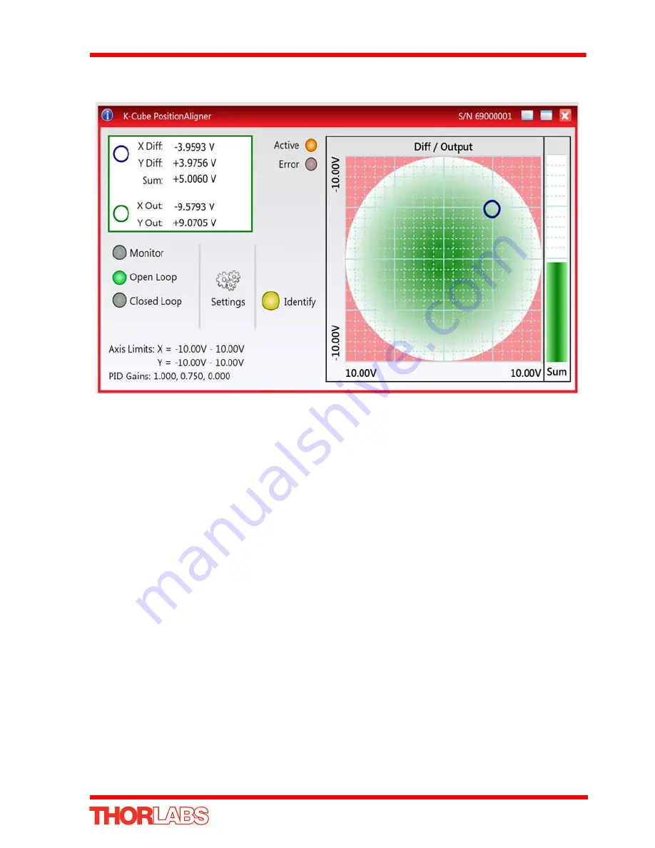
When the unit is switched to closed loop mode, the spot moves towards the center of
the display as the piezo units drive the piezo mirror to reposition the laser beam.
Fig. 5.10 Repositioning the Laser Beam
But the X Out and Y Out values are nearly ‘10’, which means that the piezos are near
the limit of their travel. The system cannot drive the piezo mirror further and has not
managed to move the laser spot to the centre of the detector. The piezo actuators
must be recentered (i.e. OUTPUT pot adjusted for 37.5V display), and the position
error taken up by manual adjustment.
10)Press the OPEN LOOP button on the GUI panel to select ‘Open Loop’ mode.
11)Adjust the OUTPUT pot on the piezo drivers GUI until both displays read 37.5 V.
12)Adjust the manual actuators on the turn ing mirror as necessary to position the
laser beam in the detector array.
13)Press the MODE button on the position aligner to select ‘Closed Loop’ mode.


