Optical Microscopy Course Kit
Chapter 5: Setup and Adjustment
Page 38
MTN015225-D02
4. Place the assembly into the benchtop organizer for storage.
5.2.16
LED and Multi-Purpose Mount Assembly
1. Screw four SMR05 (SMR05/M) optic mounts onto four TR4 (TR100/M) posts.
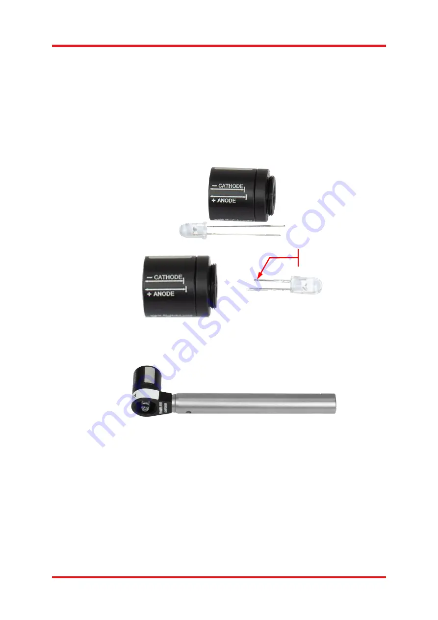
2. Use the arrow markings on the barrel of the LEDMT1F LED mount (62
Ω resistor) as a template to cut the
leads of the LED631E LED to the appropriate length. It is best to shorten them as shown below, such that
the leads have noticeably different lengths, in order to tell the anode apart from cathode; to avoid
confusion, shorten the smaller arm first. Once trimmed, slowly insert the LED into the LED mount. If it gets
stuck before it is fully inserted, wiggle it or unplug the LED again then reinsert. The LED should go all the
way into the mount.
3. Use the
provided “Red” label and add it to the SMR05 (SMR05/M) mount. Alternately, you can label the
LED mount itself in the provided white labeling area, using a permanent marker.
4. Screw the LED mount into one of the SMR05 (SMR05/M) post mounted optic holders.
5. Take an LEDMT1E LED mount (
51 Ω resistor) and repeat the two previous steps with the LED405E LED,
then repeat with the LED528EHP LED and LED940E LED. Add the
“Blue,” “Green,” and “IR” labels,
respectively, to the LEDs. To reiterate:
a. The red LED (item # LED631E) goes into the LEDM1F mount.
b. All the other LEDs go into the LEDM1E mounts, which have a different current-limiting resistor.
6. Check the LEDs Blue, Green, Red with the provided USB cable and the DS5 power supply or any available
USB port. An example is show.
Trimmed LED Legs Still
Indicate the Polarity
Содержание EDU-OMC1
Страница 1: ...Rev C October 1 2020 Optical Microscopy Course EDU OMC1 EDU OMC1 M User Guide...
Страница 2: ......
Страница 4: ......
Страница 59: ......
Страница 60: ...www thorlabs com...


