44
HA0277T Rev H Dec 2016
Chapter 5
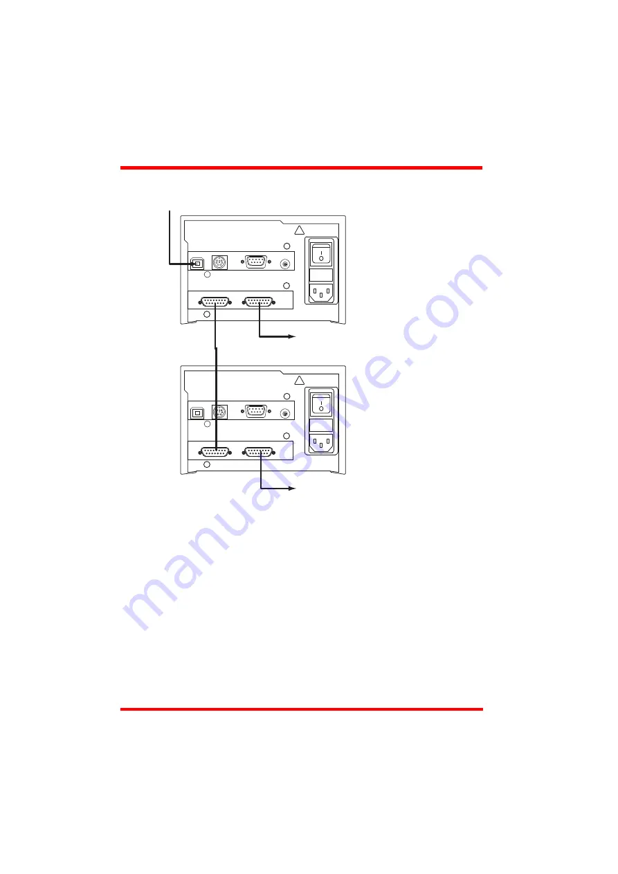
For example, consider the following diagram:
Fig. 5.8 Typical Triggering Set Up
When the move command is received via the USB link, the motor associated with unit
A starts to move by the specified relative distance. Unit A also sends a trigger signal
to Unit B. Unit B has been set to 'Trig In', so on receipt of the trigger from unit A, the
associated motor also starts to move.
Persist Settings to Hardware -
The
Triggering
parameters described earlier can be
stored (persisted) within the unit itself, such that when the unit is next powered up
these settings are applied automatically. This is particularly important when the driver
is being used manually via a joystick, in the absence of a PC and USB link.
To save the settings to hardware, check the ‘Persist Settings to Hardware’ checkbox
before clicking the ‘OK button.
move
command
motor 1 move
motor 2 move
motor unit B
motor unit A
Triggering Parameter setup
Motor Unit A (Master)
Trigger Mode
- Trig Out
Move Type
- Relative
Motor Unit B (Slave)
Trigger Mode
- Trig In
Move Type
- Relative
Initiate move on Motor
Unit A via software or GUI,
!
CONTROL IO
MOTOR DRIVE
FUSES F1 and F2
T2A
ANTISURGE CERAMIC
85 - 264 VAC
47 - 63Hz 150VA
!
CONTROL IO
MOTOR DRIVE
FUSES F1 and F2
T2A
ANTISURGE CERAMIC
85 - 264 VAC
47 - 63Hz 150VA
Trigger Out
pin 12
Trigger In
pin 4
USB
HANDSET IN
INTERCONNECT
CH ID
USB
HANDSET IN
INTERCONNECT
CH ID


