


Form RZ-NA-I-FT, Page 8
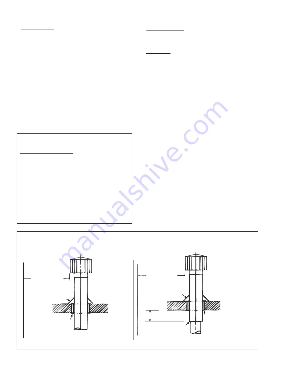
Figure 7A - Vertical Vent Terminals
11. Venting Requirements (cont'd)
6 (2M) minimum
6 (2M) minimum
Approved clearance thimble
for single-wall vent pipe is
required when flue pipe
extends through
combustible materials.
Parapet or Adjoining Building
Vertical flue extension to
be 6 (152mm) higher than
anticipated snow depth but
no less than 2 feet (610mm)
above the roof.
Vertical pipe extension
must be insulated.
Roof Flashing
Roof - pitched
from 0 to 45°
Vertical flue extension
to be 6 (152mm) higher
than anticipated snow
depth but no less than
2 feet (610mm) above the
roof.
6 (152mm) minimum
Roof Flashing
Roof - pitched
from 0 to 45°
Approved clearance thimble
is required when flue pipe
extends through combustible
materials. Follow the require-
ments of the double-wall pipe
manufacturer.
Follow instructions above
to join single and double-wall
pipe and to seal the connection.
Parapet or Adjoining Building
Single-Wall Vent Run
and Single-Wall
Terminal End
Single-Wall Vent Run
and Double-Wall
Terminal End
5. Vent System Support
- Lateral runs should be supported every six
feet using a non-combustible material, such as strap steel or chain. Do
not rely on the heater for support of either horizontal or vertical vent
pipe.
6. Condensation
- On Model Sizes 30 and 45 only, if a single-wall vent
pipe run exceeds 15 feet (4.6 M) of straight length, it is recommended
that the pipe be insulated along its entire length with a minimum of 1/2"
foil-faced fiberglass, 1-1/2# density insulation rated for 250°F.
On all Model Sizes, any length of single-wall vent pipe exposed to cold
air or run through an unheated area or an area with an ambient tempera-
ture of 45°F or less must be insulated along its entire length with a
minimum of 1/2" foil-faced fiberglass, 1-1/2# density insulation. Model
Sizes 30 and 45 require insulation rated for 250°F; Model Sizes 60-300
require insulation rated for 400°F.
Where extreme conditions are anticipated, install a means of condensate
disposal.
7. Vent Terminal (Pipe and Vent Cap) -
The vent system must be
terminated with the type of vent cap approved for use with this heater.
The vent cap must be the same size as the vent pipe (vent pipe is either
3", 4", 5" or 6" diameter). Heaters must be equipped with the heater
manufacturer's vent cap, a Type L Breidert
Air-x-hauster
®
vent cap, or
equivalent. A different style vent cap could cause nuisance problems or
unsafe conditions.
See the illustrations in Figures 7A and 7B for requirements of vertical
and horizontal vent termination. The vent terminal pipe may be either
single-wall or double-wall (Type B). If double-wall pipe is used in the
vent terminal with a single-wall vent run, follow the instructions in
"Vent System Joints" (in the left column) to attach the vent cap and to
connect the double-wall pipe to the single-wall vent pipe run.
4. Vent System Joints
- Vent system joints depend on the type of pipe
being used (See "Vent Pipe" requirements, No.1).
•
If using single wall, 26-gauge or heavier galvanized pipe, secure
slip-fit connections using sheetmetal screws or rivets. Seal pipe joints
either with tape suitable for 550°F (such as Option FA1, P/N 98266)
or high-temperature silicone sealant.
If using single-wall pipe to install a horizontal vent on a residential
application (Figure 6), make the elbow rigid by adding a light bead
of silicone sealant to the full circumference of
all
elbow section
joints.
•
If using Category III vent pipe, follow the pipe manufacturer's in-
structions for joining pipe sections. When attaching Category III
pipe to the venter outlet or the vent cap, make secure, sealed joints
following a procedure that best suits the style of Category III pipe
being used.
•
If using double-wall (Type B) vent pipe, follow the pipe
manufacturer's instructions for joining pipe sections.
For joining double-wall pipe to the venter outlet collar, increaser
collar, single-wall pipe, and/or the vent cap, follow the "boxed"
instructions below:
Instructions for attaching double-wall (Type B) vent pipe to the
venter outlet, a single-wall pipe run, or to the vent cap (use these
instructions for either full length double-wall or terminal only)
:
Hardware and Sealant Required: 3/4" long sheetmetal screws; and
a tube of silicone sealant
1) Look for the "flow" arrow on the vent pipe; attach according to
the arrow. Slide the pipe so that the venter outlet, the single-wall
pipe, or the vent cap is inside the double-wall pipe.
2) Drill a hole through the pipe into the outlet collar, the single-wall
pipe, or the vent cap. (Hole should be slightly smaller than the
sheetmetal screw being used.) Using a 3/4" long sheetmetal screw,
attach the pipe. Do not overtighten. Repeat, drilling and inserting
two additional screws evenly spaced (120° apart) around the pipe.
3) Use sealant to seal any gaps. If there is an annular opening, run a
large bead of sealant in the opening. The bead of sealant must be
large enough to seal the opening, but it is not necessary to fill the
full volume of the annular area.