


SETUP Function
This function provides access to a series of sub menus that will allow the configuration of the entire system. In this
section, each feature of the
SETUP
menu is discussed in detail along with a diagram of each VFD display.
Note:
A complete step-by-step speaker configuration setup guide is located on page 15.
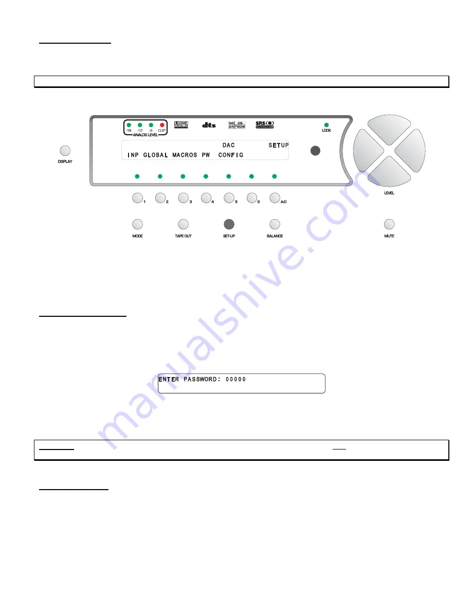
Pressing the
SET-UP
button once changes the front panel display to the first page of the
SETUP
menu, shown in
figure 20.
Figure 20 - Front Panel Display of the SETUP Menu
As indicated in figure 20, button
1
is assigned to features that are stored by input and leads to a series of categorized
sub menus via 3 pages. Button #
2
accesses all submenus and parameters that are not programmable by input select
button, or in other words, global features. Button #
3
accesses the
MACROS
sub menu and button #
4
allows the user
to password protect all
SETUP
features. Button #
5
displays the configuration of the installed DAC cards.
Setup Button Password
It is possible to password protect the entire
SETUP
function, or have no password at all. If a password is set here, the
user will be asked to enter the 5 digit password whenever the
SETUP
function is accessed. Setting a password for the
SET-UP
button is accessed by pressing button #
4
, where the user will be asked “
ARE YOU SURE YOU WANT TO
ENTER A PASSWORD FOR THIS MENU?
” Answering “
YES
” by pressing the
A-D
button will display the following
page:
Figure 21 - Front Panel Display of the SETUP
/
Assign Password Display
Use buttons
1
-
6
to assign a password. If no password is to be used (factory default), press the
A-D
button five times,
which enters all zeros. All zeros, or a zero anywhere in the password translates to no password.
CAUTION
: It is imperative that your new password be written down. If it is forgotten, ALL access to the
SETUP
menu
will be denied. Please see the
WARNING
on page 14.
DAC Configuration
Pressing button #
5
allows the user to view the channels assigned to each DAC card. This is an information page only
and not an editable menu. As an example, the first page will say “
LEFT FRONT CEN
” if a three channel Standard or
Superior balanced DAC card is in DAC slot # 1. Press the
A-D
button to view which channels are assigned to the
second DAC card, and
A-D
once more for the third DAC card, if any. Press
SET-UP
once to exit this menu.
The following section will discuss all menus and parameters under the
INPUT
button.
47
Содержание Casablanca III
Страница 1: ...THETA DIGITAL C O R P O R A T I O N Casablanca III Owner s Manual V 3 00 Rev A a Digital Done Right ...
Страница 16: ...Casablanca III Block Diagram DAC and Analog Out Sections Figure 4 Block Diagram of DAC and Analog Outputs 6 ...
Страница 23: ...13 Setup Menus and Pages Figure 14 Setup Menus and Pages ...
Страница 25: ...15 STEP BY STEP SETUP GUIDE ...
Страница 34: ...24 Setup Flowcharts A P Flowchart A Setup Subwoofer s ...
Страница 35: ...Flowchart B Front Left Right Configuration 25 ...
Страница 36: ...Flowchart C Front Center Configuration 26 ...
Страница 37: ...Flowchart D Left Right Surround Configuration 27 ...
Страница 38: ...Flowchart E Surround Center Configuration 28 ...
Страница 39: ...Flowchart F Sides Configuration 29 ...
Страница 40: ...Flowchart G Setup Speaker Levels 30 ...
Страница 41: ...Flowchart H Setup Speaker Delays 31 ...
Страница 42: ...Flowchart I Setup Dolby Digital 32 ...
Страница 43: ...Flowchart J Setup DTS 33 ...
Страница 44: ...Flowchart K Setup Circle Surround 34 ...
Страница 45: ...Flowchart L Copy Input Speaker Parameters 35 ...
Страница 46: ...Flowchart M Setup Default Mode 36 ...
Страница 47: ...Flowchart N Setup Post Process 37 ...
Страница 48: ...Flowchart O Map Input Jacks 38 ...
Страница 49: ...Flowchart P Setup Analog Input Levels 39 ...
Страница 88: ...REMOTE CONTROL 78 ...
Страница 114: ...APPENDIXES 104 ...
Страница 120: ...Figure 115 Wiring diagram for the Casablanca III Digital Output board and a 6 Channel External Volume Control unit 110 ...


