(
PULSE
). The specification sheet for the device connected to the remote power jack should contain information as to
which type of signal it requires, and if it is a pulse, the minimum pulse duration.
The output signal of the remote power jack does not need to be delayed since its activation is by the user via either the
hand held remote or front panel
REMOTE
button.
Buttons
2
,
3
and
4
have exactly the same functionality as button
1
, except that they apply for the three
MAIN
POWER
jacks on the rear panel.
The
MAIN POWER 1
jack is activated immediately upon exiting the standby mode (pressing the front panel or the
hand held remote
POWER
button), the
MAIN POWER 2
jack is activated
X
seconds after exiting standby and the
MAIN POWER 3
jack is activated
X
times 2 seconds after exiting standby.
X
represents the time, in seconds, that is
set by pressing button #
5
–
MTIM
, or Main [Delay] Time. This is useful for sequencing the turn on of high power
components such as amplifiers. Further to this, when the Casablanca III is put into standby, it can be set that all of the
MAIN POWER
jacks turn off simultaneously or sequenced off in the opposite order as they were activated.
Sequencing is accomplished by setting
SEQ
(button #
6
) to
ON
or
OFF
. By setting the
SEQ
parameter to
ON
, the
user is activating the power down sequencer.
If the type of output for any of the rear panel power jacks is set to
PULSE
, the duration (in milliseconds) of this pulse
can be set by the user, by selecting the
A-D
button and using the
LEVEL
UP
/
DOWN
buttons to change the pulse
duration.
*The current limiting resistor is 33 ohms, 0. 5W. This means that the more current a device to be triggered draws, the
more the output voltage gets reduced. The formula is : Output voltage =12 – (I x 33), where I = the current draw from
the triggered device, in Amperes. Refer to the device’s manual for this information. The Casablanca III’s maximum
output current is 100mA, which, by using the above formula, means that with a 100mA draw, the output voltage will be
8.7 volts, although most triggered circuits have virtually no current draw.
Clear Balance (Temporary Settings Control)
Any changes in the
BALANCE
menus are, by default, temporary. That is to say that when an
INPUT
SELECT
button
is pressed or the Casablanca III is powered down/put into standby, any changes will be reset to zero. This feature has
an override, which is set by pressing button #
4
in the first
SETUP
/
GLOBAL
page (figure
52
on page 67) and set to
OFF
. When this parameter is set to
OFF
, changing inputs or powering down/going into standby will maintain all
BALANCE
menu settings.
RS232
In the first
SETUP
/
GLOBAL
page, press button #
5
to access the
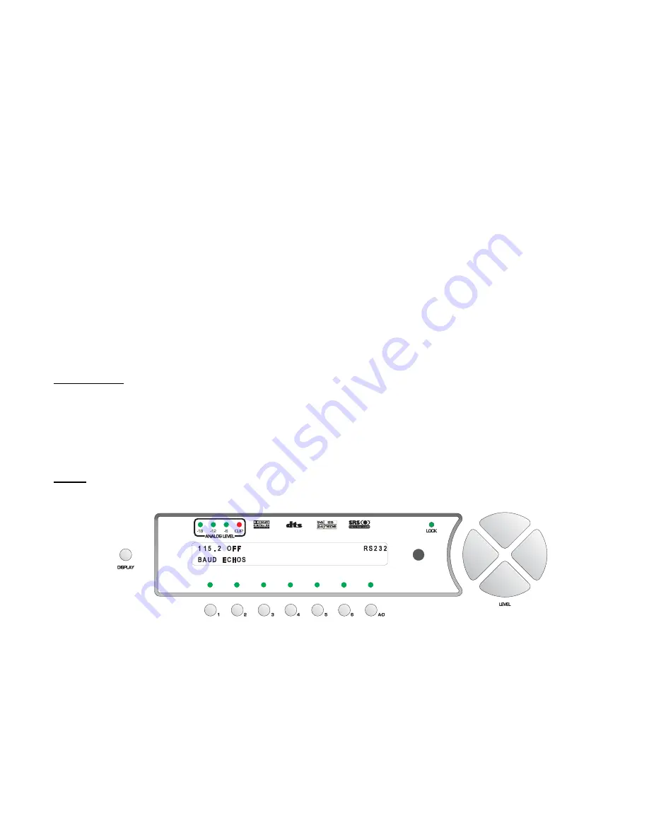
RS232
sub menu shown in figure 56.
Figure 56 - Front Panel Display of the SETUP
/
GLOBAL
/
RS232 Sub Menu
Press button #
1
(
BAUD
) and use the
LEVEL UP
/
DOWN
buttons to select the Baud rate that matches that of the
RS232 controller. The factory default value is 115.2K
The Casablanca III can be set to automatically send changes to the RS232 port. This can be done by selecting a
“Status Level”, which means if any Casablanca III parameter changes, that level's bytes will be sent to the port. This is
useful for monitoring master level, input and the like when the user has access to both the Casablanca III and the
touch-panel controller, to keep them synchronized.
Button #
2
(
ECHOS
) [Echo Status] allows the user to enable or disable the output of data to the RS232 port and, if
enabled, determine which level, or pre-determined group of bytes it outputs. Setting this value to
OFF
disables any
parameter change information from being output to the RS232 port.
69
Содержание Casablanca III
Страница 1: ...THETA DIGITAL C O R P O R A T I O N Casablanca III Owner s Manual V 3 00 Rev A a Digital Done Right ...
Страница 16: ...Casablanca III Block Diagram DAC and Analog Out Sections Figure 4 Block Diagram of DAC and Analog Outputs 6 ...
Страница 23: ...13 Setup Menus and Pages Figure 14 Setup Menus and Pages ...
Страница 25: ...15 STEP BY STEP SETUP GUIDE ...
Страница 34: ...24 Setup Flowcharts A P Flowchart A Setup Subwoofer s ...
Страница 35: ...Flowchart B Front Left Right Configuration 25 ...
Страница 36: ...Flowchart C Front Center Configuration 26 ...
Страница 37: ...Flowchart D Left Right Surround Configuration 27 ...
Страница 38: ...Flowchart E Surround Center Configuration 28 ...
Страница 39: ...Flowchart F Sides Configuration 29 ...
Страница 40: ...Flowchart G Setup Speaker Levels 30 ...
Страница 41: ...Flowchart H Setup Speaker Delays 31 ...
Страница 42: ...Flowchart I Setup Dolby Digital 32 ...
Страница 43: ...Flowchart J Setup DTS 33 ...
Страница 44: ...Flowchart K Setup Circle Surround 34 ...
Страница 45: ...Flowchart L Copy Input Speaker Parameters 35 ...
Страница 46: ...Flowchart M Setup Default Mode 36 ...
Страница 47: ...Flowchart N Setup Post Process 37 ...
Страница 48: ...Flowchart O Map Input Jacks 38 ...
Страница 49: ...Flowchart P Setup Analog Input Levels 39 ...
Страница 88: ...REMOTE CONTROL 78 ...
Страница 114: ...APPENDIXES 104 ...
Страница 120: ...Figure 115 Wiring diagram for the Casablanca III Digital Output board and a 6 Channel External Volume Control unit 110 ...


