Thermo Scientific
8-1
8
Communication Option
The Communication Option enables digital communication between the UT150
controller and a PC. It is a factory-installed temperature controller and cable
assembly using an RS-485 connection through a DB9 cable.
This option is supplied with the necessary cable and diagnostic software to set up
and check the connections between the unit and the PC. Follow the steps below to
make the cable connections and to check the data transfer. If you have purchased
the “SpecView Plus Communication Software” with the copy protection key, refer
to the SpecView instructions in parallel with this setup outline.
Cable Installation
1. To install the 25-foot external cable, disconnect the electrical power from both
the unit and PC.
2. Connect the cable end with a black housing to the 9-pin port on the rear of the
Thermo Fisher Scientific unit.
3. Connect the other cable end with the RS-232/485 converter to the COM 1 Port
(or other COM port of your choice) on the rear of the PC.
4. If you have purchased the Spec View Plus Communication Software with the
copy protection key, install this key on your parallel port. It may be necessary
to locate the key between a cable and the parallel port.
5. Apply electrical power to the unit and the PC.
UT150 Communications Setup Parameters
UT150 Communication Parameters
shows the default values for UT150
Communications Setup Parameters. To access these parameter:
1. Hold the SET/ENT button for three second to display the Operating
Parameters. Press and release the SET/ENT button to display the “LoC”
parameter. Assure lower value at “ø”. Press the down arrow to show “-1” in the
lower display and press SET/ENT to acknowledge and enter the Setup
Parameter menu.
2. Press and release the SET/ENT button to access the six parameters specific to
communication option.
Содержание BF51841BC
Страница 1: ......
Страница 6: ...List of Figures ii Thermo Scientific ...
Страница 18: ...Safety Notes Standards and Directives 1 12 Thermo Scientific ...
Страница 22: ...Unpacking Unpacking 3 2 Thermo Scientific ...
Страница 28: ...Installation Shelf Installation in Box Furnaces 4 6 Thermo Scientific ...
Страница 38: ...Correction of Temperature Overshoot 6 8 Thermo Scientific ...
Страница 42: ...Excess Temperature Option B Model Excess Temperature Controller Operation 7 4 Thermo Scientific ...
Страница 48: ...Communication Option Addresses for Multiple Controllers 8 6 Thermo Scientific ...
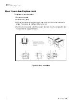
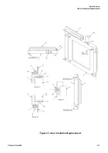
Страница 55: ...Maintenance Door Insulation Replacement Thermo Scientific 9 7 Figure 11 Door Insulation Replacement ...
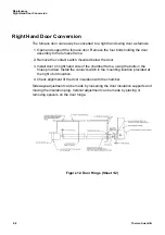
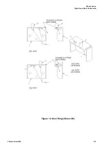
Страница 57: ...Maintenance Right Hand Door Conversion Thermo Scientific 9 9 Figure 12 Door Hinge Sheet 2 2 ...
Страница 63: ...Replacement Parts Thermo Scientific 11 3 Figure 13 Wiring Diagram ...
Страница 64: ...Replacement Parts 11 4 Thermo Scientific ...
Страница 65: ...Thermo Scientific 12 1 12 Error Codes This chapter is not applicable ...
Страница 66: ...Error Codes 12 2 Thermo Scientific ...
Страница 68: ...WEEE Compliance 13 2 Thermo Scientific ...
Страница 69: ...Thermo Scientific 14 1 14 14 Spare Parts and Accessories This chapter is not applicable ...
Страница 70: ...Spare Parts and Accessories 14 2 Thermo Scientific ...
Страница 72: ...Device Log 15 2 Thermo Scientific ...


