23
23
23
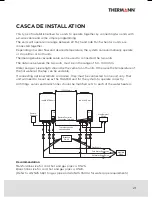
Hook up the
interconnect cable
to the remote
controller terminal
of each unit.
Set the Dip Switch 2 on the
PCB of each unit (MASTER
unit and SLAVE unit).
Please refer to Step 3, page 22
If connecting the remote
controller, all remote controllers
should be connected with the
MASTER unit.
Energize the SLAVE first.
Then, energize the MASTER unit.
Follow initial setting
of remote controllers
on page 18
Normal operation
Normal operation
Is the remote controller
connected?
Is the remote
controller’s initial setting
done?
735 error on
display?
No indication on
display?
15 flashes
repeated at 3 sec
intervals?
Flashes at irregular
intervals?
More
than 25 times
flashes continue?
Disconnect power to
MASTER unit and SLAVE unit
CHECK
- Is Cascade cable properly connected?
- Is Dip Switch 2 setting correct?
Checked
3 minute wait
No
No
No
No
No
No
No
Yes
Yes
Yes
Yes
Yes
Yes
Yes
CHECK THE
COMBUSTION INDICATOR LED
CASCADE INSTALLATION FLOWCHART
Содержание 26LP50C
Страница 2: ...Thermann Installer s Manual Gas Continuous Flow Condensing Water Heaters ...
Страница 27: ...27 27 27 ...
Страница 28: ...20832270 K ...

