Owner's Manual
Top Actuator Operation & Top Strike Positioning
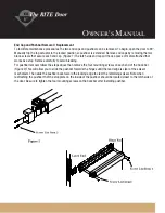
Proper operation of this device relies heavily on the correct adjustment of the top actuator. The strike is designed
to be operated with a minimum of 1/16" between top of door and frame. The diagram below (Figure A) shows the
correct relationship of the square bolt to the top actuator. The square bolt must be flush with the stop plate. There are
four #10-32 x 1/2" Phillips head screws that are in slotted holes in the top channel of the door that keep the actuator
secured. These will have to be removed to adjust the square bolt.
The square bolt can be adjusted up or down (CW to lower - CCW to raise) so that it is flush with the stop plate. Be
sure that the square bolt is not too high, as this will cause the actuator to rock in the channel. The pins in the square
bolt (Figure B) must be turned in the proper direction to fit through the slot in actuator. After the square bolt has been
adjusted, hand tighten the four mounting screws.
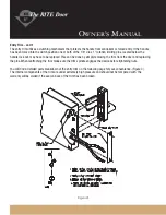
The top strike must be properly located, and tightened securely, for the device to operate correctly. **A minimum
1/16" between top of door and frame is required. Position the top strike so that it is centered on the hole cutout.
(Figure D) Tip the strike post into the hole and hand tighten. Depress the pushbar to open the top latch actuator.
Slowly close the door so that the top actuator and strike engage. This technique will self align the components.
Depress the pushbar and open the door slowly. Tighten the top strike post with the allen wrench and also secure
the top actuator by tightening the four mounting screws (Figure C).
Содержание D3676
Страница 7: ...Owner s Manual...
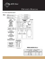
Страница 10: ...Owner s Manual PS LR Power Supply Wiring Diagram...


