Owner's Manual
Latch Retraction (LR) Devices
Electric latch retraction is an available feature for The RITE Door
®
. The LR option provides for electric latch retraction
from a remote location. All D3676LR, D3677LR & D8576LR devices are required to be operated with the D-PS-LR
Adams Rite power supply. This power supply will provide the necessary 16 Amperes of current @28VDC required to
operate these devices. The power supply features dual system retraction, allowing independent or sequential control
for up to two devices. Fire alarm interface and auxiliary power source outputs are also standard features on the
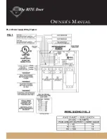
power supply. The D-PS-LR power supply is equipped with automatic door interface circuitry. Refer to the diagram
inside the access panel of the D-PS-LR power supply or on the following page for wiring of the devices and auxiliary
outputs.
Troubleshooting
If and when a problem with the Electric Latch Retraction system occurs some troubleshooting tips for the units are
given here for your convenience. A qualified installer or electrician is recommended to repair any electrical problems
that may be encountered. Before proceeding through the trouble shooting section, ensure that exit device latches
are not binding against their corresponding strikes. A bound latch can cause sluggish electric retraction or prevent
retraction entirely.
Neither Exit Device Retracts After The Control Switch is Activated
Ensure exit device wires are properly terminated in the power supply. Verify continuity through power transfer devices such as
wired hinges and door cords/loops.
"Main Power" Red LED Is Not Lit
Verify line voltage is present. Check fuse F2 (in the black fuse holder). Ensure that the Primary Voltage Selection Switch SW2 is
properly set.
"Output Power" LED On Power Supply Board Is Not Lit
Check fuse F1. If fuse F1 is blown, the wires that are run to the exit device are probably shorted together against the conduit,
door frame, or electric hinge. Use a meter to check for shorts. There is no Fire Alarm connection between J3-9 and J3-10 or the
factory installed jumper between J3-9 and J3-10 is removed.
IN1 And IN2 lights Do Not Light In Response To Input Switches
An open connection in the field wiring exists between the Adams Rite Power Supply and control switch used for activating the
latch solenoids. A defective control switch exists on J3-1 and J3-2 or J3-3 and J3-4.
OUT1 And OUT2 Lights Do Light In Response To Input Switches
An open connection in the field wiring between the Adams Rite Power Supply and the exit device may exist. Do a resistance
check to verify. If previous suggestions do not solve the problem, and one EXIT DEVICE works and one does not, prop the door
open and connect a voltmeter across the BLACK and WHITE leads coming from the exit device. Next, activate the malfunctioning
Exit Device. If the voltmeter measures approximately 28VDC at the time of activation, but the latch did not budge, then the two
wire driver is not generating pulses to the PULL coil of the solenoid. The exit device must be replaced.
Devices Retract Even Though The Control Switch Had Not Been Activated
A maintain control switch is being used and is in the closed position. Control switch is defective - Disconnect switch to verify.
Buzzing Sound Is Coming From Inside The Exit Device
The latch is binding against its corresponding strike and preventing it from retracting fully due to misalignment between the
latch and strike opening.
Содержание D3676
Страница 7: ...Owner s Manual...
Страница 10: ...Owner s Manual PS LR Power Supply Wiring Diagram...


