Page 8
CL-B101D40HZ Manual (d0098)
Operational Display
SETPOINT SETTING
AND RELAY
CONFIGURATION MODE
STEP A
STEP B
STEP C
STEP D
No [doM] or [dob]
No [doM] or [dob]
STEP E
STEP F
STEP G
STEP H
STEP I
STEP J
STEP K
STEP L
To Step M of Setpoint
Setting and Relay
Configuration Page 9
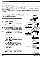
The following programming steps are required to enter the setpoint values and configure the relay functions
in a meter with four relays using four setpoints. Generally if less than four relays are installed, the setpoints
without relays are operational in software for tri-color control or display only purposes. To remove unwanted
setpoint indications, set them to 9999 or -1999 depending on the relay activation mode selected.
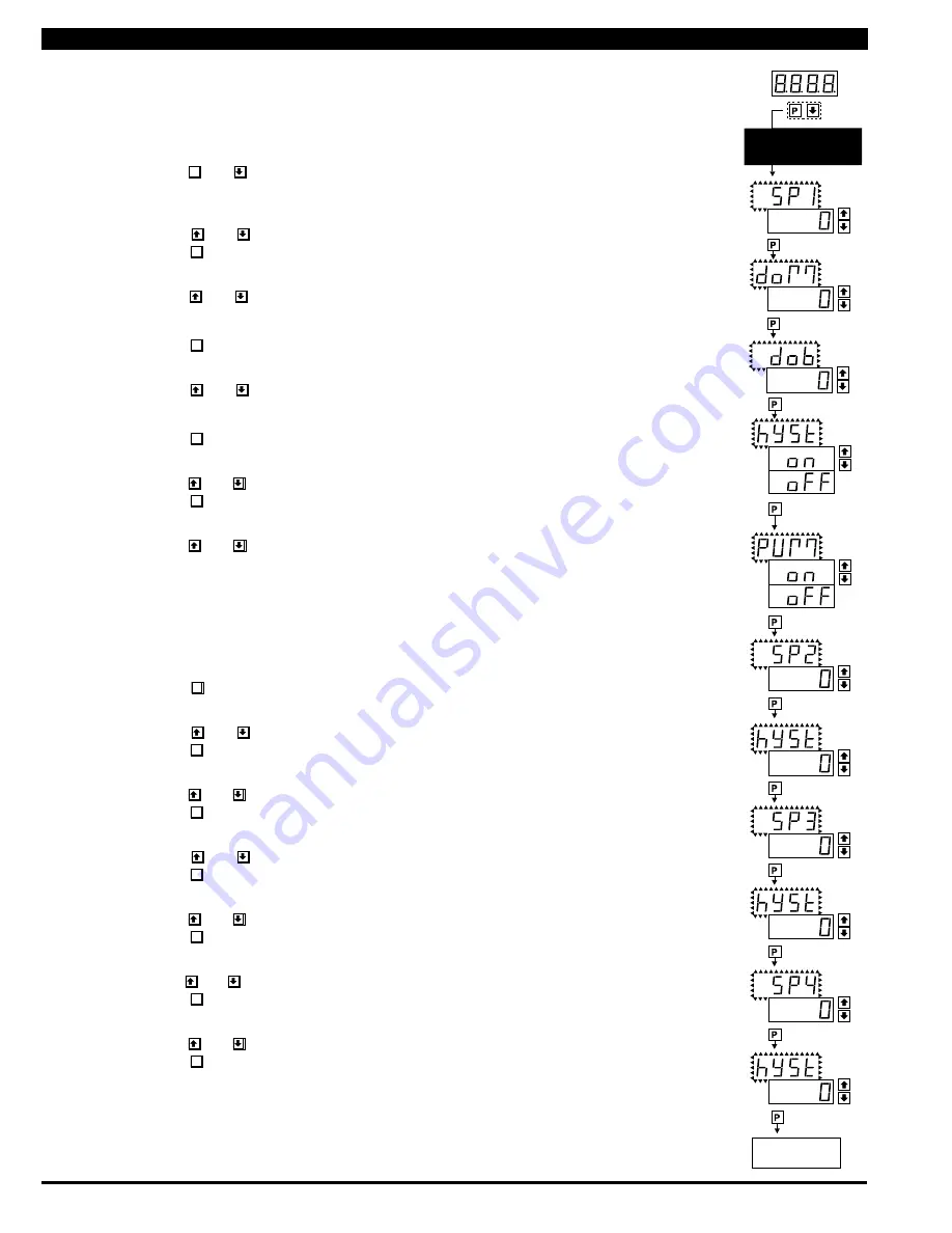
STEP A Enter the Setpoint Mode
1) Press the
P
and
buttons at the same time. Display toggles between [SP1] and the previous
SP1 setting.
STEP B Set Setpoint 1 [SP1]
1) Using the and
buttons, adjust the display to the desired SP1 value.
2) Press the
P
button. Display toggles between [doM] and the previous [doM] setting.
STEP C Set the SP1 Delay-on-Make [doM] Delay Time Setting
1)
Using the and
buttons, adjust the display to the desired [doM] value (0 to 9999 seconds).
The reading must continuously remain in an alarm condition until this delay time has elapsed before
the relay will make contact (energize).
2) Press the
P
button. Display toggles between [dob] and the previous [dob] setting.
STEP D Set the SP1 Delay-on-Break [dob] Delay Time Setting
1)
Using the and
buttons, adjust the display to the desired [dob] value (0 to 9999 seconds).
The reading must continuously remain in a non-alarm condition until this delay time has elapsed
before the relay will break contact (de-energize).
2) Press the
P
button. Display toggles between [hYSt] and the previous [hYSt] setting.
STEP E Select the Hysteresis [hYSt]
1)
Using the and
buttons, select the Hysteresis to be ON or OFF.
2) Press the
P
button. Display toggles between PUM and (on) or (oFF).
STEP F Select Pump [PUM] (on) or (oFF)
1)
Using the and
buttons, select the Pump to be ON or OFF. When PUM is selected ON, and
SP2 is set at a value higher than SP1, the SP1 relay will operate in a special "pump on pump off" mode.
SP2 acts as the upper limit and SP1 acts as the lower limit of the Hysteresis Band on the SP1 relay.
For filling applications:
[rLYS] should be set to [LhXX] (see step M). The SP1 relay and SP1 LED Annunciator will then activate for inputs
less than the SP1 setpoint, and remain ON until the SP2 setpoint is reached.
For emptying applications:
[rLYS] should be set to [hhXX] (see step M). The SP1 relay and SP1 LED Annunciator will then activate for inputs
greater than the SP2 setpoint, and remain ON until the SP1 setpoint is reached.
2) Press the
P
button. Display toggles between [SP2] and the previous SP2 setting.
STEP G Set Setpoint 2 (SP2)
1) Using the and
buttons, adjust the display to the desired SP2 value.
2) Press the
P
button. Display toggles between [hySt] and the previous [hySt] setting.
STEP H Select the Hysteresis [hYSt]
1)
Using the and
buttons, select the Hysteresis to be ON or OFF.
2) Press the
P
button. Display toggles between [SP3] and the previous [SP3] setting.
STEP I Set Setpoint 3 (SP3) (No [doM] or [dob])
1) Using the and
buttons, adjust the display to the desired SP3 value.
2) Press the
P
button. Display toggles between [hySt] and the previous [hySt] setting.
STEP J Select the Hysteresis [hYSt]
1)
Using the and
buttons, select the Hysteresis to be ON or OFF.
2) Press the
P
button. Display toggles between [SP4] and the previous [SP4] setting.
STEP K Set Setpoint 4 (SP4) (No [doM] or [dob])
1)
Using the and
buttons, adjust the display to the desired SP4 value.
2) Press the
P
button. Display toggles between [hySt] and the previous [hySt] setting.
STEP L Select the Hysteresis [hYSt]
1)
Using the and
buttons, select the Hysteresis to be ON or OFF.
2) Press the
P
button. Display toggles between [rLYS] and the previous relay setting.
Please Continue On Next Page.
Setpoint Setting and Relay Configuration Mode


