Other Functions
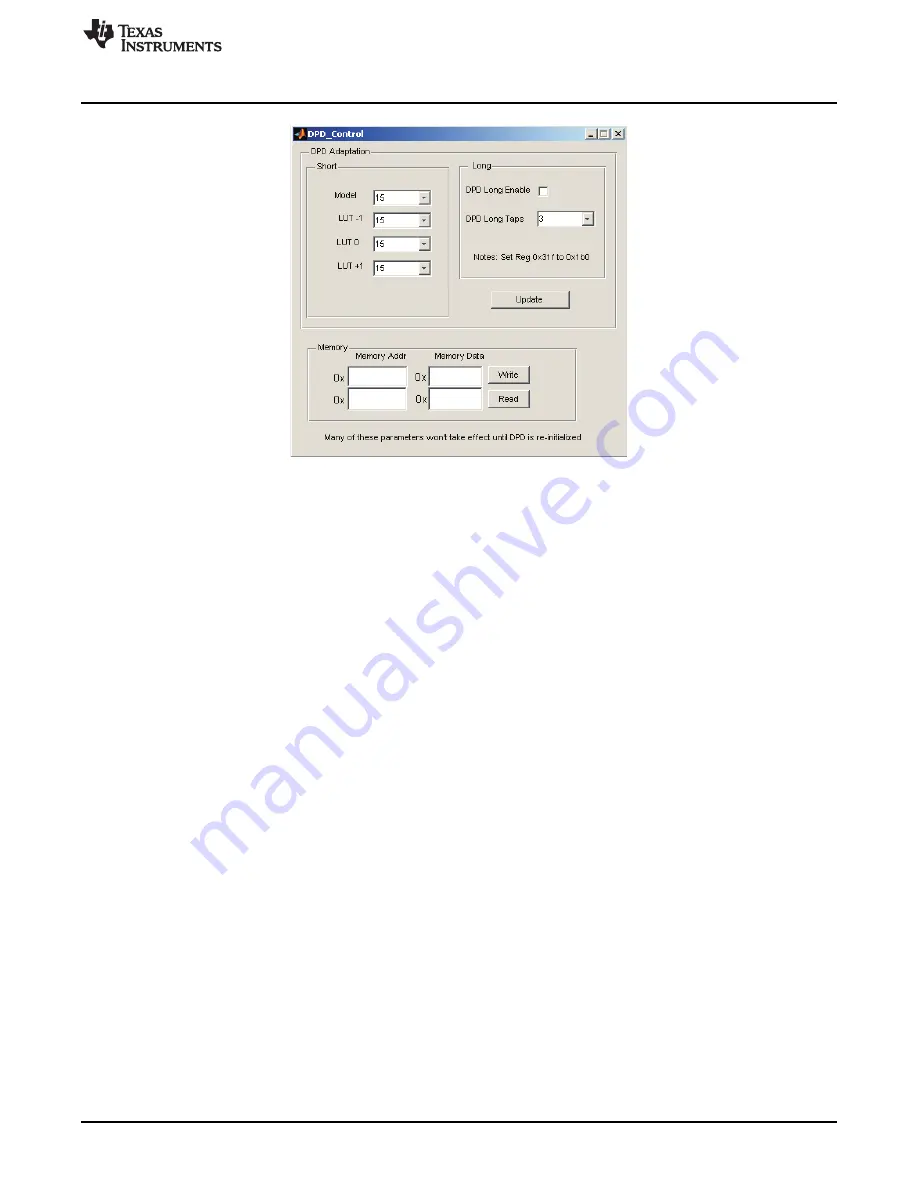
Figure 27. DPD Control Window
ET Control - Will be addressed in a future application note.
5.10 Capture Buffers
The Capture Buffers window allows the user to capture 4K of data from different points of processing
within the GC5325. The GC5325 contains two 4K capture buffers which will store the data that is selected
by the user. The Capture Buffers are the 4 plots located on the right side of the GUI. The top two displays
(time and frequency) use data from one capture buffer and the bottom two displays use data from the
other buffer. The top two displays show the DPD output data. This is the pre-distorted signal data from the
transmit buffer. The bottom two displays show the feedback output data. This is the feedback buffer
complex data that is converted to baseband. The following can be viewed when they are selected and the
"External Plots" box is selected:
Selecting "DPD Input" displays the data captured by the input buffer which feeds the DPD algorithm.
Selecting "FB Input" displays the input buffer at the feedback (ADC).
Selecting "Error" displays the Feedback signal compared to the original TX signal from the TSW3100.
External plots allows external plots to be plotted and saved.
ErrPwr - This button displays the error power between the TX and RX buffers.
AM + PM - This button makes either a PA AM-AM (amplitude vs amplitude) plot, as shown in
, or
a AM-PM plot (amplitude vs phase). The blue curve was taken before DPD. The green and red ones were
taken after DPD. The plot will hold the previous plots and overlay any new plots that are taken. To clear
existing plots, close the plot and start over.
The AM-AM plot shows the normalized amplitude variation at the PA output over the range of the signal
amplitudes at the PA input. The X axis is the range of the input amplitudes, and the Y axis is the variation
in amplitude at the PA output. This gives an indication of the amplitude response of the PA at a particular
operating point. For a PA that is linear, the amplitude variations would be close to 0 dB across all input
amplitude ranges since the normalized PA output tracks the PA input. As the PA starts to operate near
saturation, the PA output response may show both compression and expansion effects which is reflected
in the AM-AM plot. The larger amplitude variations at the smaller signal levels are mainly due to
normalization of small errors to even smaller signal amplitudes.
The AM-PM plot is similar to the AM-AM plot. However, the AM-PM plot shows the phase variation of the
output signal relative to the phase of the input signal over the range of input signal levels.
27
SLWU063F
–
April 2009
–
Revised April 2011
GC5325 System Evaluation Kit
Copyright
©
2009
–
2011, Texas Instruments Incorporated


