


device may have a different default configuration. The communication mode can be changed by programming
either the register or OTP configuration. The customer can program the device's integrated OTP on the
manufacturing line to set the desired communications speed and protocol to be used at power up in operation.
14.2 I
2
C Communications
The I
2
C serial communications interface in the BQ769142 device acts as a slave device and supports rates up to
400 kHz with an optional CRC check. If the OTP has not been programmed, the BQ769142 device will initially
power up by default in 400 kHz I
2
C mode, although other versions of the device may initially power up in a
different mode, as described in the
. The OTP setting can be programmed on the
manufacturing line, then when the device powers up, it will automatically enter the selected mode per OTP
setting. The host can also change the I
2
C speed setting while in CONFIG_UPDATE mode, then the new speed
setting will take effect upon exit of CONFIG_UPDATE mode. Alternatively, the host can use the
SWAP_TO_I2C()
subcommand to change the communications interface to I
2
C immediately.
The I
2
C device address (as an 8-bit value including slave address and R/W bit) is set by default as 0x10 (write),
0x11 (read), which can be changed by configuration setting.
The communications interface includes programmable timeout capability, this should only be used if the bus will
be operating at 100 kHz or 400 kHz. If this is enabled with the device set to 100 kHz mode, then the device will
reset the communications interface logic if a clock is detected low longer than a t
TIMEOUT
of 25 ms to 35 ms, or if
the cumulative clock low slave extend time exceeds ≈25 ms, or if the cumulative clock low master extend time
exceeds 10 ms. If the timeouts are enabled with the device set to 400 kHz mode, then the device will reset the
communications interface logic if a clock is detected low longer than t
TIMEOUT
of 5 ms to 20 ms. The bus also
includes a long-term timeout if the SCL pin is detected low for more than 2 seconds, which applies whether or
not the timeouts above are enabled.
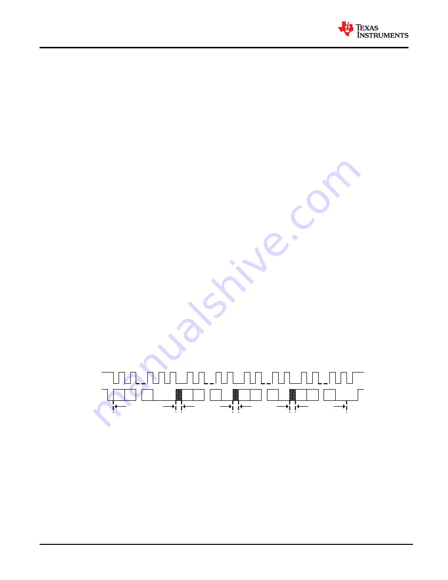
shows an I
2
C write transaction. Block writes are allowed by sending additional data bytes before the
Stop. The I
2
C logic autoincrement the register address after each data byte.
When enabled, the CRC is calculated as follows:
• In a single-byte write transaction, the CRC is calculated over the slave address, register address, and data.
• In a block write transaction, the CRC for the first data byte is calculated over the slave address, register
address, and data. The CRC for subsequent data bytes is calculated over the data byte only.
The CRC polynomial is x
8
+ x
2
+ x + 1, and the initial value is 0.
When the slave detects an invalid CRC, the I
2
C slave will NACK the CRC, which causes the I
2
C slave to go to
an idle state.
A7
A6
A1
...
R7
R/W
R6
R0
...
D7 D6
D0
...
C7 C6
C0
...
Start
Slave Address
Register
Address
Data
CRC
(optional)
Stop
SCL
SDA
ACK
ACK
ACK
ACK
Figure 14-1. I
2
C Write
shows a read transaction using a Repeated Start.
SLUSE91A – SEPTEMBER 2020 – REVISED FEBRUARY 2021
52
Copyright © 2021 Texas Instruments Incorporated
Product Folder Links:
Содержание BQ769142
Страница 79: ......


