background image

3.6.2  Scanner mode setup wizard 
 

 Use 

the 

LBP

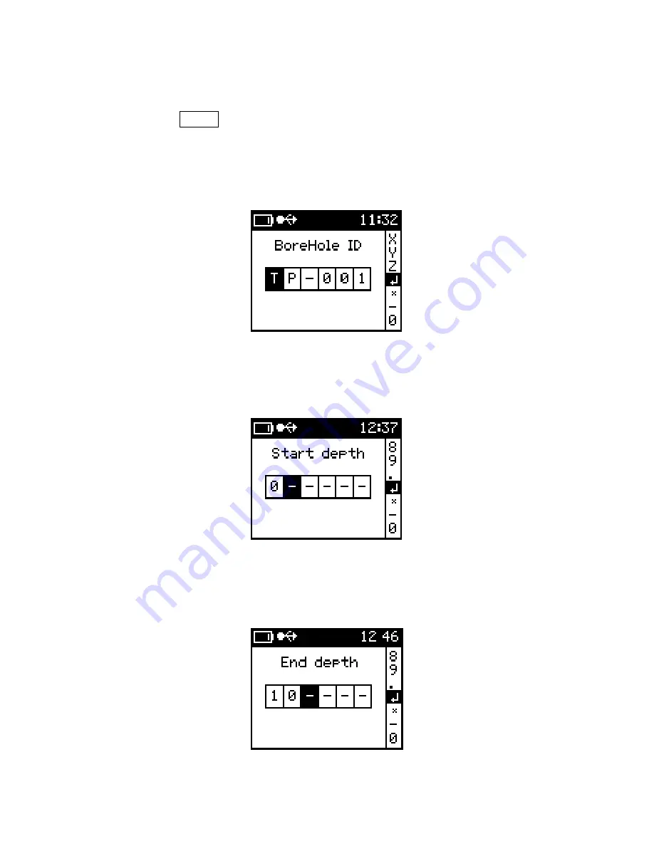
 to select the Scanner mode.  The Scanner setup wizard will be 


activated as shown below. 


1)


BoreHole ID 


Use the alpha-numeric to enter identification for the borehole 


BoreHole ID 


2)


Start Depth 


Enter the starting depth of the core 


Start Depth 


3)


End Depth 


Enter the End depth of the core 


End Depth 


41

Содержание KT-10 v2 C

Страница 1: ...KT 10 v2 Magnetic Susceptibility Conductivity and Combined Magnetic Susceptibility Conductivity Meter with User s Guide Ver 2 1 Phone 905 764 5505 Fax 905 764 8093 Web http www terraplus ca ...

Страница 2: ...lar or rectangular coil The basic KT 10 v2 can also be upgraded to include extended magnetic susceptibility conductivity and or extended conductivity measurements All upgrades can be performed via the internet Please contact Terraplus Sales Department at sales terraplus ca for further information This User s guide describes the operation of the meter as a combined magnetic susceptibility conductiv...

Страница 3: ...age 10 2 3 Layout Page 13 2 4 Controls Page 14 2 5 Menus Page 15 2 6 Icons Page 16 Chapter 3 Operating the KT 10 v2 3 1 Battery Installation Page 17 3 2 Power Page 18 3 2 1 Power On Page 18 3 2 2 Power Off Page 18 3 3 Setup Menu Page 19 3 4 Measure Page 25 3 4 1 Taking a reading Page 25 3 4 2 Storing a reading Page 27 3 4 3 Measurement Sub Menu Page 29 3 4 4 Measure Flow Chart Page 30 3 4 5 Measur...

Страница 4: ... 3 6 4 Discrete mode setup Wizard Page 46 3 6 5 Discrete mode measurement Page 47 3 7 Voice Recorder Page 49 3 8 PIN Installation Page 50 Chapter 4 Software 4 1 GeoView Page 53 4 1 1 Installation Page 53 4 1 2 GeoView Calendar Interface Page 60 4 1 3 GeoView Data Interface Page 66 4 1 4 Data Download Page 67 4 1 5 Data Export Page 69 4 1 6 Borehole Mode data Display Page 75 4 1 7 Device Settings P...

Страница 5: ... 2 3 Graph Scale Page 100 5 2 4 Zoom Pan Page 102 5 2 5 Delete Data Page 102 Chapter 6 Troubleshooting 6 1 Note about switching off Page 103 6 2 Meter turns off during measurement Page 103 6 3 Error on screen Page 104 6 4 Maintenance Page 105 6 5 Contact Technical Support Page 105 Appendix A KT 10 v2 Plus feature Page 106 Appendix B Advice Recommandations Page 114 5 ...

Страница 6: ...This page is intentionally left blank 6 ...

Страница 7: ...s capable of measuring uneven rock surfaces and is well suited for automated drill core logging with a digitally recorded scanning mode With its leading edge technology the KT 10 v2 offers high sensitivity higher operational comfort and excellent communication capabilities IMPORTANT Your KT 10 v2 meter is calibrated at the factory and a periodic calibration is not required 1 2 Operating Principle ...

Страница 8: ...increases and vice versa Our method is based on the analysis of this change 1 2 2 Operating principle The KT 10 v2 utilizes a 10 kHz LC oscillator with an inductive coil to measure the magnetic susceptibility and conductivity Magnetic susceptibility is calculated from the frequency difference between the sample and free air measurements while conductivity is calculated from the difference in ampli...

Страница 9: ...aged together and 4 readings per second are stored Display High Contrast LCD Graphic Display with 104 x 88 pixels Memory Up to 4000 measurements with voice notes Control One button with up and down functionality A PIN mode is available for rough surfaces Communication USB Bluetooth and GPS link via Bluetooth Battery Two AA batteries Rechargeable or Non rechargeable Battery life Up to 3000 readings...

Страница 10: ...display field measurements records in the KT 10 v2 memory The keypad of the smart phone can be used to enter additional text notes to the current data or any previously stored data on the KT 10 v2 True Susceptibility and Conductivity The KT 10 v2 uses automated correcting routines to display true susceptibility and volume conductivity Uneven Samples The KT 10 v2 is offered with a PIN for rough sur...

Страница 11: ...n Cond Sucs mode the audio will reflect the intensity of the Conductivity measurements The voice recorder allows the recording and replaying of voice messages through the loudspeaker as well Data Storage The KT 10 v2 can store up to 4000 measurements with two minutes of comments per reading to its internal non volatile memory Average readings and standard deviation are also stored The operator can...

Страница 12: ...On screen notification icons allows the operator to monitor the battery status Bluetooth connectivity GPS support and more Power Power saving techniques and use of low consumption components allow for the use of high speed communication standards USB Bluetooth and supports the large LCD display The meter is powered by 2 AA type batteries The user can use any brand of rechargeable or non rechargeab...

Страница 13: ...2 3 KT 10 v2 Layout LCD Graphic Display Microphone Associated Button Up Down Oscillator Coil Battery Port USB Communication Loud Speaker Figure 1 KT 10 v2 Layout KT 10 S C shown 13 ...

Страница 14: ...ears on display This symbol will be used throughout this document to represent this button press LBP Short Button Press DOWN is a single short push on the button pointing away from screen in its lower half This symbol will be used throughout this document to represent this button press SBP Long Button Press DOWN hold the button in its lower half for more than one second or until a reaction appears...

Страница 15: ...n the main menu will appear shown in Figure 4 Figure 4 Main Menu Measure and Scanner are the two modes of operation for the KT 10 v2 Selecting one of these options will activate the measurement routine for that mode Setup is used to configure mode date time core size selection connection of Bluetooth GPS unit and battery type selection along with calibration information Shutdown will turn the unit...

Страница 16: ...isplayed in this location and are displayed permanently during operation of the instrument Below you will find a list of the other icons you will see used on the meter and the meaning for each of them Pin used for measurement Readings have been saved Button used for measurement USB is connected Core diameter selected Bluetooth is connected GPS is connecting GPS is connected Voice Note 16 ...

Страница 17: ... flathead screw driver or suitable coin to open the lid 3 Insert two rechargeable AA cell batteries provided The positive side goes in first 4 Close the battery housing by screwing the lid back onto it 5 Attach the rubber protective cover back in position Note If you are going to store your KT 10 v2 for long a period of time please remove the batteries from the unit to prevent damage from electrol...

Страница 18: ... unit off use LBP or LBP on the Shutdown option from the main menu You will be presented with the following screen Figure 7 Power Off Alternatively Press SBP and SBP together to turn the meter off at any time during operation The shut down screen will not appear Instead the unit will immediately turn off TIP Place your finger or thumb tip between the two buttons to simplify this task 18 ...

Страница 19: ... SBP then when the parameter is highlighted use LBP or LBP to activate it Figure 8 Setup Menu Mode Optional for KT 10 v2 KT 10 v2 can be operated in 3 different configurations measure Magnetic Susceptibility and Conductivity simultaneously measure only Magnetic Susceptibility or measure Conductivity only For ease of operation the user can select from 4 modes Susceptibility Conductivity Susceptibil...

Страница 20: ... readings Average Std Deviation Average Scanner Max Figure 10 a Measure Mode Figure 10 b Scanner Mode Cond Enables the meter for conductivity measurements Along with conductivity results user can obtain data average and standard deviation values in the measure mode and data average and maximum values in the scanner mode seen in Figure 11 of readings Average Std Deviation Average Scanner Max Figure...

Страница 21: ...Figure 12 of readings Average Std Deviation Average Scanner Max Figure 12 a Measure Mode Figure 12 b Scanner Mode Cond Susc This mode will enable the meter to read both conductivity and susceptibility simultaneously In this mode measurement of conductivity is considered primary and the results of the primary are displayed in large text User can obtain data average and standard deviation values in ...

Страница 22: ...non standard diameters are available When a diameter is selected for either full cylindrical or split cores the diameter correction is automatically applied to magnetic susceptibility and conductivity measurements Figure 15 Core diameter Concentration Conc Tables for Plus model only see page 106 The user can choose to obtain readings in either basic SI or CGS units or as a grade estimate in a perc...

Страница 23: ... when all the Bluetooth enabled devices have been detected a list of all named Bluetooth devices will be displayed Please consult the GPS user s manual for detailed information on settings for the Bluetooth GPS and any name it may use for its discovery Please note Some Bluetooth GPS units require a PIN for secure pairing To facilitate this the KT 10 v2 allows entry of a PIN via GeoView software Ba...

Страница 24: ...in both the Measure and the Scanner mode In the Setup menu the Borehole mode option can be OFF or ON When the Borehole mode is ON the main menu will list Borehole as a method of measurement Borehole Mode OFF Borehole Mode ON Main Menu Units Users can obtain magnetic susceptibility measurements in either SI or CGS units while conductivity measurements can be in either S m or Ω m units When Borehole...

Страница 25: ...Figure 21 Start Measure When you enter the measurement mode the screen above will be displayed and indicate that the meter is ready to start the measurement process There are three steps involved in the measurement sequence the first step is a free air measurement the second is the sample measurement and the final step is another free air measurement Note The duration for the measurement sequence ...

Страница 26: ...that the meter is position in a free air space void of all metallic objects Step 1 With the KT 10 v2 in free air use SBP to start the measurement process After about 1 second you will hear a short sound indicating the free air measurements are complete Step 2 Immediately place the KT 10 v2 on the sample s surface then use SBP When the reading on the sample is complete you will hear a sound this so...

Страница 27: ...asurements Step 3 Then immediately position the KT 10 v2 in free air once again for the final free air measurements Wait for the final sound which will be the same as the first tone heard in Step 1 This sound will indicate the final free air measurements are complete and the reading s will be displayed on screen 3 4 2 Store a reading To store the reading there are two different options available q...

Страница 28: ... its contents to be confirmed User can then store or discard the voice note Figure 23 Store voice record When a reading is stored by either method a confirmation will be displayed It will show the record number date and time along with any GPS positions available if the optional Bluetooth GPS is enabled Figure 24 Record Saved 28 ...

Страница 29: ...measure will return the display to the results page This is accomplished with the use of SBP or SBP to highlight the selection and use LBP or LBP to select it Disable GPS will remove the GPS positions from the data set However the meter will remain paired to the Bluetooth GPS Highlight this option by moving the cursor with SBP or SBP and once highlighted select it with LBP or LBP When you return t...

Страница 30: ...ure 45 61 10 3 SI Ø 1 56 21 0 04 SBP SBP LBP LBP Start Measurement without Storing Readings Store Current Values Measure Menu Start Voice Recording Measure Core Sequence Figure 20 Back to Measurement Screen Data Stored Store Store with Note Continue Measure Clear Average Main Menu Recording On SBP RECORDING OFF AUTO REPLAY LBP LBP Figure 26 Measurement Flow 30 ...

Страница 31: ...ore this time has elapsed Figure 27 Measurement Sequence BEEP 1 BEEP 2 BEEP 1 SBP AIR MEASUREMENT HAS BEEN FINISHED POSITION THE KT 10 v2 TO YOUR SAMPLE AND TRIGGER WITH SBP MEAS SAMPLE MEAS AIR 1 AIR MEASUREMENT IN PROGRESS MEAS AIR 2 SAMPLE MEASUREMENT HAS BEEN COMPLETED MOVE METER FROM SAMPLE INTO FREE AIR AND WAIT UNTIL THE MEASUREMENTS ARE DISPLAYED MEAS 45 61 AVG cnt 56 21 4 ...

Страница 32: ...tup menu b Select Mode and select the preferred mode of measurement c Select Core diameter then choose a core diameter size Select None if you are measuring rock samples d Select Back to menu to return to the main menu 2 Select Scanner Ensure the meter is on the start scanner screen that is displayed in Figure 28 Before proceeding with the measurements ensure that the meter is positioned in free a...

Страница 33: ...Scanner process Soon after you will hear a short sound indicating the free air measurements are complete and that the meter can be positioned on the sample Step 2 Begin to move the KT 10 v2 along the surface you wish to measure The meter s loud speaker will indicate the relative intensity of the reading by the pitch of the audio Place a marker in the data set with SBP Use SBP at any time during th...

Страница 34: ...ll invoke the voice recorder and the screen shown in Figure 29 will be displayed Position the KT 10 v2 about 10 cm from your mouth and speak at a normal volume You can end the voice record by using either SBP or SBP or by allowing the time to elapse 45 seconds Figure 29 Voice Record Once the recording has ended it will automatically be replayed this will allow its contents to be confirmed User can...

Страница 35: ...d Record 3 5 3 Measurement Sub Menu The measurement menu can be accessed only when the results are displayed on the screen this is accomplished by a SBP as shown in Figure 32 This menu allows for the storing of the reading storing of the reading with a voice note returning to the measure routine disabling the GPS if GPS connected clearing the average or returning to the main menu Figure 32 Scanner...

Страница 36: ...l return the display to the results page This is accomplished with the use of SBP or SBP to highlight the selection and a LBP or LBP to select it Disable GPS will remove the GPS positions from the data set However the meter will remain paired to the Bluetooth GPS Highlight this option by moving the cursor with SBP or SBP and once highlighted select it with LBP or LBP When you return to the measure...

Страница 37: ...g On RECORDING OFF AUTO REPLAY SBP LBP or _ _ _ _ Start Scanner SBP SBP LBP LBP Back to Measurement Screen Scanner Sequence Figure 27 Store Current Values Measure Menu Data Stored Store Store with Note Continue Measure Clear Average Main Menu Start Voice Recording Start Scanner without Current Values Stored 45 61 10 3 SI Ø 1 56 21 0 04 Figure 33 Scanner Measurement Flow 37 ...

Страница 38: ...ELY 0 5 SECONDS SBP ADDS A MARKER IN DATA STREAM ADDS A MARKER IN DATA STREAM SBP SBP STOP SCANNER ADDS A MARKER IN DATA STREAM SBP 38 3 5 5 Scanner Sequence AIR SAMPLE END BEEP 2 Figure 34 Scanner Measurement Sequence BEEP 2 BEEP 2 BEEP 1 ...

Страница 39: ... the SBP is used to activate the Scanner measurement sequence and to add depth interval to the data set Depth intervals can be recorded with the push of a button while scanning cores All readings between depth intervals are interpolated 3 6 1 Borehole mode configuration 1 Enable Borehole mode a From the main menu select Setup options b Select Borehole mode and then enable it by selecting On c Sele...

Страница 40: ...le Selecting new borehole will start the Borehole creation wizard Up to six alphas numerical characters can be used to enter the Borehole options Use the SBP or SBP to scroll through the characters and LBP or LBP to make selection a selection The symbol is used to proceeded to next in the setup wizard and the symbol is used to exit the setup wizard Use the for a space or to make corrections 5 Sele...

Страница 41: ...de The Scanner setup wizard will be activated as shown below 1 BoreHole ID Use the alpha numeric to enter identification for the borehole BoreHole ID 2 Start Depth Enter the starting depth of the core Start Depth 3 End Depth Enter the End depth of the core End Depth 41 ...

Страница 42: ...hat are in a core box of Cores in a Box 6 Depth Interval Enter depth interval for the core Depth Interval The Borehole setup wizard is now completed there will be a brief message on the screen indicating that the new borehole is loaded and does not have any readings recorded for this borehole 42 ...

Страница 43: ... last for 120 seconds unless stopped with the use of SBP To start the measurement process follow the steps listed below Ensure your KT 10 v2 is positioned in free air space void of all metallic objects before proceeding with measurement Step 1 With the KT 10 v2 in free air use SBP to start the Scanner process Soon after you will hear a short sound indicating the free air measurements are complete ...

Страница 44: ...P or else the data will not correspond to the depth properly Step 3 Begin to move the KT 10 v2 along the surface you wish to measure The meter s loud speaker will indicate the relative intensity of the reading by the loudness of the audio To insert a depth interval in the data set use SBP The scanner will automatically come to a stop when all depth intervals are accounted for given core length as ...

Страница 45: ...ved In case of more than one Core box the after completion of the first core box the meter will automatically will be configured for the next core box with the appropriate start depth without any intervention from the user Step 5 Use the SBP to continue scanning rest of the cores When all of the cores have been scanned and saved a message showing borehole complete will be displayed as shown on the...

Страница 46: ... readings The operator will be able to associate the Borehole ID and the Depth interval to each new reading collected In this mode the depth interval is used as constant for incrementing depth for each successive reading If a New borehole is not already been selected use SBP or SBP to highlight this mode in the borehole options and select it with the use of LBP or LBP Use SBP or SBP to highlight t...

Страница 47: ...al Enter the depth interval as desired Depth Interval 3 6 5 Taking a measurement in Discrete mode Start Measure Discrete mode After completion of the borehole setup wizard the screen above will be displayed indicating that the meter is ready to start the measurement process 47 ...

Страница 48: ...ep 1 With the KT 10 v2 in free air use SBP to start the measurement process After about 1 second you will hear a short sound indicating the free air measurements are complete Step 2 Immediately place the KT 10 v2 on the sample s surface then use SBP When the reading on the sample is complete you will hear a sound this sound is different than the one heard during the free air measurements Step 3 Im...

Страница 49: ... the file is played back Using SBP will end the voice recording Note voice notes are currently limited to 45 seconds per recording The voice recorder can add complimentary information to a set of core measurements or field measurements For example the voice recorder will allow an operator to indicate which borehole a reading came from as well as any other location information if the optional GPS i...

Страница 50: ...s There will be a single PIN located in the carrying case at the time of purchase located near the back left as seen below Figure 35 PIN Storage Figure 35 KT 10 v2 Pouch PIN Storage Note A spare PIN can be purchased and carried in the KT 10 v2 Pouch as shown in Figure 35 50 ...

Страница 51: ...PIN Rubber protector PIN Figure 36 PIN Remove the thread protector screw from the head of the KT 10 v2 Coil Cap PIN Thread Protector Screw Figure 37 Coil Cap Thread Protector 51 ...

Страница 52: ...When the thread protector have been removed insert the KT 10 v2 PIN into the center hole where the thread protector came from seen in the image on the left Coil Cap and PIN installed 52 ...

Страница 53: ...hat are recorded and stored on the KT 10 v2 s internal memory can be replayed from with in the software interface This allows for the voice notes and visual observations that have been recorded from the field to be added and stored along side the readings from the KT 10 v2 for a complete picture 4 1 1 Installation To install GeoView locate the install package provided to you on the KT 10 v2 softwa...

Страница 54: ...eoView software To begin installation select the appropriate option from the menu shown below Figure 40 Figure 40 Install Splash Screen USB Driver Installation Please ensure that the meter is not connected to the PC via USB prior to driver installation When selecting Install Georadis USB driver you will be presented with the following screen seen in Figure 41 select Next to continue the installati...

Страница 55: ... copy the files to the appropriate location Windows will respond by showing you that a new USB device has been recognized The new hardware wizard will start Note You should be logged in as an administrator to complete this part of the install Figure 43 Windows New Hardware Wizard You will not need to go to the internet as the previous step has copied the files to your PC already so select No not a...

Страница 56: ...ftware automatically and then press Next button The drivers will start to be copied to the windows system32 drivers folder but you may be warned that the drivers have not passed Windows Verification Figure 45 Start File Copy Select Continue Anyways 56 ...

Страница 57: ...l be able to establish communication between your PC and the KT 10 v2 Figure 47 Driver Files Copied GeoView Installation When selecting Install Georadis GeoView you will be presented with the screen as seen in Figure 48 select Next to continue the installation or Cancel to exit 57 ...

Страница 58: ...lt C Program Files Geoview or use the browse button to find a new directory to install the GeoView software too Select Next when the correct path has been chosen Figure 49 Folder Location You will then confirm the destination folder by selecting Install or if you wish to change this location use the Back button to make the necessary changes 58 ...

Страница 59: ...llation progress window seen in Figure 51 will then be presented which is followed by a confirmation dialogue seen in Figure 52 Selecting Finish completes the installation process Figure 51 Install progress window Figure 52 GeoView Installation Complete 59 ...

Страница 60: ...53 GeoView Icon Figure 54 Calendar Interface Let us get acquainted with the GeoView calendar interface As is the case with most Windows software programs there are menus located at the top row of the main window On GeoView these are labelled File Device and Program Under each menu are several selections which are outlined below in detail Some of these selections that are used most often also have ...

Страница 61: ... can use the default database name FBD or choose a name for the database Seen in Figure 55 is the dialog for this task Enter the desired name and then press the Save button when complete Figure 55 Create Local Database Open local database This will open an already created local database which contains data from one or many KT 10 v2 units Select the database file that you wish to work with and then...

Страница 62: ...ote database option to work correctly for further details please contact Terraplus Technical Support for assistance Contact information can be found on the last page of this manual Open remote database This will open an already created remote database which contains data from one or many KT 10 v2 units Fill in the server name path to the database file and then press the open button to connect to t...

Страница 63: ...en below Connect to Device Icon Disconnect device Disconnect your Personal Computer from a KT 10 v2 s USB or Bluetooth connection icon seen below Disconnect from Device Icon Download data Begin the process to download data from a connected KT 10 v2 icon seen below Further details on this can be found in section 4 1 4 Data download on Page 67 Download data Icon Device settings Open the device setti...

Страница 64: ... a quick link icon to this feature and it can be seen below About Geoview Icon Directly below the quick link icons you will see a pull down menu with a date beside it This can be seen below in Figure 60 This allows you to switch between different years in the database You will also notice two tabs one labelled Calendar and the other labelled Measured data which are directly above the year This wil...

Страница 65: ...her Create local database or Create remote database Most users will want to use the local database option Figure 62 File Menu A Windows file browser window will open seen in Figure 63 Select the location and file name for the database file Select Save when finished Figure 63 Database Creation Dialogue You will notice at the bottom of the main window that a database connection is now shown Figure 6...

Страница 66: ...interface The displayed date has two buttons on either side of it These two buttons allow for you to move forwards and backwards through the calendar while remaining in the data view display Please note Only days that contain data for the serial number shown will be viewable To the right of the date you will see a pull down menu which contains a serial number list of unit s with data being display...

Страница 67: ... will open prompting you to select the method and serial number for the unit you are connecting to Figure 66 Connection dialog USB Bluetooth The tabs at the top of the window are used to select either a USB connection or Bluetooth connection The unit you have connected to your Personal Computer will show up in the list In the case of a Bluetooth connection you may have to use the discover button t...

Страница 68: ...ded and the dialogue box display will show the details of the operation The display will change depending on which type of readings is being downloaded The record total of records will be presented when data is being downloaded and Downloading note will be displayed when downloading a voice record The Unique record ID will be used for referencing voice notes to the recorded readings Figure 57 Down...

Страница 69: ...le instruments are used on the same day these are also separated and a list of serial numbers will be presented on that day Figure 70 Calendar with Data Populated To view the data on any of the days double click on the day or click once on the day and select the Measure data tab 4 1 5 Data Export When the icon is pressed the window of Figure 71 will open This dialogue is used to select the data th...

Страница 70: ...window will open to choose the location seen in Figure 72 Select a location and then press OK then the Export button to complete the task Figure 72 Data Export Location Window The final icon on this row is used to add notes or information to the day These will be displayed directly to the right of this icon when populated Over on the right hand side of the window you will notice two more icons Thi...

Страница 71: ...e types of data that can be added to the database and these are Integer numbers Real numbers and String data Each data type has a name and a description associated with it and the user must define these when setting up the custom fields With the numerical data you also have the ability to add a range of acceptable values with values outside this range being rejected at entry To add custom fields t...

Страница 72: ...ction The different windows can be seen in Figures 76 77 and 78 Figure 76 Integer field setup Figure 77 Real number field setup Figure 78 String Setup Give the field a name and brief description for numerical values provide the range of valid entries When complete select the Add field button at the bottom to complete the task Repeat these steps for each new field that is to be added to the databas...

Страница 73: ...the Move up and Move down to change the location of the fields in the database Edit field will allow you to change the description and number range for a field The field name cannot be changed when stored To remove fields use Delete field a confirmation window will be presented to confirm the deletion of the field Scanner records will also be listed in the upper numerical display and are blue in c...

Страница 74: ...on highlighted will be seen as the entire graph plot An example of this can be seen below in Figure 82 Figure 82 Zooming on Scanner Graph The next two buttons are for zooming in and out Left click on the button to increase the zoom level and left click on the button to decrease the zoom level To reset the zoom level to default and look at the entire scan record use the button To apply an auto scal...

Страница 75: ...core in time Partial Borehole Shows graphical view of a single scanned core in time Whole Borehole Shows graphical view of the entire cores or records collected for a given borehole The graph is plotted with depth information Discrete mode Measure mode For the discrete mode the displayed data parameters are the core box number depth and the reading values for susceptibility and conductivity The bo...

Страница 76: ...later use or loaded from a file to be sent to the KT 10 v2 With the exception of the GPS PIN setting each will only have two options available The GPS PIN setting should be used when a Bluetooth GPS is to be used with the KT 10 v2 and has a documented PIN Pairing Identification Number or Personal Identification Number Consult with the documentation for your GPS to find this PIN and enter the numbe...

Страница 77: ...ll format the complete memory on the KT 10 v2 and all data will be lost Figure 85 Memory Read The Maintenance window has a firmware upgrade process and an additional assistance method which can be used to assist persons in the field to correct issues that may be un foreseen Session to maintainer is used for just this purpose This will send the parameters file from the KT 10 v2 unit to the manufact...

Страница 78: ...e end user to enjoy new software features and or correct any bug in the current firmware CAUTION Failure to follow the upgrade instructions exactly could render the unit inoperative requiring an RMA and a return to repair Please follow the upgrade instructions explicitly When selecting Firmware Upgrade as seen in figure 86 you will be presented with the following screen seen in Figure 87 select Ne...

Страница 79: ...y the Georaids web site If it finds a firmware that is newer than what is currently on your KT 10 v2 it will be downloaded Figure 88 New Firmware Downloaded Press Next to continue The utility will erase the current firmware and upload the new firmware on to the unit Figure 89 Firmware Uploaded to KT 10 v2 Press Next to continue 79 ...

Страница 80: ... Figure 90 It is very IMPORTANT not to disturb the unit during the upgrade process Figure 90 FW Upgrade screen Upon successful upgrade the KT 10 v2 will re start You may then press the press Finish button to exit the firmware upgrade wizard Figure 91 Firmware Update Complete 80 ...

Страница 81: ...Making changes without complete understanding or guidance from Terraplus Technical Support may result in incorrect operation of the KT 10 v2 IMPORTANT The KT 10 v2 console program cannot be executed directly from a CD ROM Please copy the console files s to local hard drive of your laptop or desktop To install the console program run geomon exe by double clicking on it When the installation wizard ...

Страница 82: ...nt destination folder if desired or click Next to continue Figure 96 Start Manu folder Select Start Menu Folder and then select Install To launch the Geomon double click on the Geomon short cut icon placed on the desktop or run it from the programs menu Figure 97 shows the Geomon software running 82 ...

Страница 83: ...Figure 97 Geomon The buttons in the menu bar are as follow Figure 98 Connect device Figure 99 Disconnect device Figure 100 About Figure 101 Quit application 83 ...

Страница 84: ... 98 3 Select device window will open up as seen in the figure below Figure 102 Select USB device 4 Highlight the serial number of your device in the box and then click on Connect The following screen will appear as seen in the figure below If the USB connection is successful the status window at the bottom of the window will show device connected Figure 103 KT 10 v2 connected 84 ...

Страница 85: ... tab offers the following Device Summary lists information such as serial number firmware version and model type of the meter that is connected Refresh updates the summary window Parameters allows user to set device parameters enter calibration value and so on Restart re starts the meter Start scanning starts scanner measurement 85 ...

Страница 86: ...s described in the section 4 1 8 on page 78 Upload file to upload tar files on the internal memory of the KT 10 v2 Purge Records permanently deletes records from the unit The tab Read Records reads all records on the device Delete record deletes individual record that is selected by the user Delete all records deletes all records on the device Export data Exports data set in text format 86 ...

Страница 87: ...Bluetooth if your PC is Bluetooth capable If you have the Bluetooth icon in the system tray of your PC you will have Bluetooth connectivity Figure 104 Bluetooth Icon By right clicking on the icon you will receive the menu below Figure 105 Add a Device Select Add Bluetooth Device and the following window will be seen 87 ...

Страница 88: ...ady to be found and then select Next Figure 107 Search for Device Allow the Bluetooth search to finish seen above When it has completed the following screen will be presented Select the KT 10 v2 with the correct serial number and choose Next Figure 108 Select Device 88 ...

Страница 89: ...No passkey is needed for the KT 10 v2 communications Bluetooth Passkey The KT 10 v2 will then be connected to your PC Installing Bluetooth Device 89 ...

Страница 90: ...9 Installation Complete Finally if you right click on the Bluetooth icon in the system tray and select show devices the KT 10 v2 will now be listed Figure 110 Confirm Bluetooth Device Further details on connecting the KT 10 v2 via Bluetooth to the GeoView software for Data Download is found in section 4 1 4 on Page 67 90 ...

Страница 91: ...ion Installation Important The software requires Android OS 2 3 3 or higher The GeoVision installation file geovision apk is located on the KT 10 v2 Utility CD inside of the Android folder Downloading the software onto your Smartphone 1 Connect your phone to computer via the USB in Mass Storage mode 2 Once connected to computer your phone s memory will appear as Removable Disk s phone s internal m...

Страница 92: ...then asked to confirm if you wish to install the application confirm it by selecting the Install button Figure 112 Confirm Installation 5 After the successful installation of the application you may either select Open or Done Selecting Open will launch the GeoVision application on your device 92 ...

Страница 93: ...Figure 113 GeoVision installed 5 2 2 GeoVision main menu Figure 114 GeoVision menu 93 ...

Страница 94: ...using the keypad of the mobile phone Connects GeoVision to the KT 10 v2 via Bluetooth 5 2 2 1 Connect Disconnect To connect GeoVision to the KT 10 v2 1 Tap on the button 2 If your phone is not currently paired with any Bluetooth device you will be provided with selection to Scan for Bluetooth device as seen in the figure below Figure 115 Scan for device 3 Tap on button 4 When the scan is completed...

Страница 95: ...on the device s name 6 When the GeoView is successfully connected to your KT 10 v2 the following screen can be seen momentarily indicating that the device is connected Figure 117 Device connected Please note that the button is now replaced with Also the Scanner button is now active 95 ...

Страница 96: ...ct button will be then replaced with Connect Figure 118 Device disconnected 5 2 2 2 Browse To browse previously stored data on the KT 10 v2 tap on the button It takes a few seconds for the GeoVision to read all of the data from the KT 10 v2 When the reading of data is completed a device log will be populated as seen in the figure below Figure 119 Device Log Note Phone 96 ...

Страница 97: ...is displayed To browse stored data tap on the serial number of the KT 10 v2 A new screen as seen in Figure 120 will be displayed listing records under Scanner and Measure tab Figure 120 Data preview To view Scanner records select Scanner in the main header and then scroll up or down to browse different scanner record 97 ...

Страница 98: ...anner record explained Note In the scanner mode 20 samples per seconds are collected Of the 20 samples 5 are averaged together total of 4 samples are stored per second The maximum number of samples for full scanner duration is 120 seconds x 4 480 To preview a scanner graph tap on the record of your choice The scanner graph will be previewed as seen in the Figure 122 below Figure 122 Scanner data p...

Страница 99: ...Tap on the scanner graph preview area to see the record in full size Figure 123 Scanner record full size Portrait view Figure 124 Scanner record full size Landscape view 99 ...

Страница 100: ...ground and susceptibility is displayed in the background By swapping layers the graph of susceptibility is now placed in the foreground and conductivity is moved to the background Automatic Sets automatic scale for the graph Y axis to ensure displayed graph is easier to read Max value 2500 Sets the maximum scale value of the Y axis to 2500 Scanner record with readings over 2500 will be clipped Max...

Страница 101: ...the Y axis to 10 Scanner record with readings over 10 will be clipped Max value 1 Sets the maximum scale value of the Y axis to 1 Scanner record with readings over 1 will be clipped Max value 0 1 Sets the maximum scale value of the Y axis to 100 Scanner record with readings over 0 1 will be clipped In the Figure 126 the function Swap Layers is used on the display to show the same graph as shown in...

Страница 102: ...rea you would like to Pan into and then bring the two fingers closer on the screen This pinching in of the two fingers for Pan can be done on both the Y and X axis 5 2 5 Delete data If you highlight and hold on a measurement record both scanner measure you will see a menu pop up for deleting record By tapping on Delete record will delete the selected record from phone s memory as well the meter if...

Страница 103: ... the unit in situation when there is no software switch accessible the way of contemporary push of button up and down every time regardless of any working status of the unit 6 2 KT 10 v2 Powers OFF during measurement Battery Confirm that the 2 AA batteries are at proper voltage level Replace if necessary Button It may be possible that both the UP and DOWN buttons are accidently being pressed at th...

Страница 104: ...easure mode 2 With the KT 10 v2 at arm s length in the free air press the UP button Meter beeps and the progress bar starts to run 3 Immediately after the first beep quickly move the KT 10 v2 to the sample s surface and press the UP button again 4 Hold the KT 10 v2 on the sample until it beeps a second time with a different tone After the second beep quickly move the instrument back to arm s lengt...

Страница 105: ... head of the KT 10 v2 can wear and tear with regular usage Spare Coil caps can be purchased through Terraplus Inc 6 5 Contact Technical Support If you are experiencing problem s with your KT 10 v2 or the application software please contact Terraplus Technical Support for assistance Our contact information is below please try to contact Terraplus Technical Support between the hours of 9 am and 5 30...

Страница 106: ...he field It can be used for sample selection core analysis and grade control With the ability to use three different calibration curves one of which is the pre installed magnetite curve users have a flexible user friendly instrument suitable for several different applications If the samples or cores have a different composition or structure than those used to create the pre installed calibration c...

Страница 107: ...bration tables The first unit of measurement Basic SI is used to obtain magnetic susceptibility measurements in SI units Under this selection measurements are displayed and stored in SI units Selecting Magnetite will enable the unit to read iron ore concentration estimates as a percentage This calibration table is based on magnetite with different concentrations The next two selections User1 User2...

Страница 108: ...to indicate which calibration table is currently being used Legend used to notify current calibration table in use 1 Magnetite 2 User1 3 User2 There will be no number shown in the notification area when the Basic SI is selected as the unit of measurement The procedure to take a reading is described in the in this user s manual and the quick user guide When a calibration table is used the measureme...

Страница 109: ...Device Parameters settings In this menu you will see a Concentration tab If there is no Concentration tab then the instrument connected to Geoview is not a Plus meter Figure 134 Concentration tab In the Concentration tab you will find the three tables that are loaded on the KT 10 Plus The Edit button will open the table for editing of the name and the calibration data points The Delete button will...

Страница 110: ...Table When creating a table you do not need to have all of the 12 data points entered for reference Smaller tables with a minimum of 4 data points can be used but they must follow a specific format In order to use a smaller table the concentration table must be padded with zeroes where there are unpopulated data points The absolute position of the table is not important but it cannot contain zeroe...

Страница 111: ...has been collected and transferred into Geoview you will see the additional information showing when the calibration curves have been used In the information column the calibration curve number is provided for each reading and is populated for any mode used with a calibration curve Figure 137 shows the results from scanner and measure modes where calibration curve 1 magnetite was used Figure 137 K...

Страница 112: ...es the more precise the measurements will be If there is a scenario where the common samples are rocks and the user does want to crush them prior to taking measurements then it is recommended to have samples with a minimum size of 4 x 4 and a thickness of 1 5 In places where the most common mineral is in a fine gravel or sand it is recommended that it be poured into a plastic 8 x 8 bag and formed ...

Страница 113: ...on and the creation of the relation table The following table is to be used only as an example Concentration Susceptibility 5 98 21 x 10 3 SI 25 405 66 x 10 3 SI 30 630 10 x 10 3 SI 40 867 72 x 10 3 SI 45 1139 23 x 10 3 SI It is recommended that multiple measurements be taken on each sample use the average value to populate the concentration table Next the user must transfer the concentration tabl...

Страница 114: ...e the influence of weathering Weathering results in a decrease of susceptibility which is intensified the more the sample is weathered It is important to remember that the coil is most strongly influenced by the rock nearest to the coil s surface even if one measures using the pin Magnetic anisotropy exists and measure parallel and perpendicular to the foliation in metamorphic rocks Make correctio...

Страница 115: ... are the responsibility of the customer Malfunctions or damages due to negligence or improper use are not covered under this warranty Users who need to send their meter to Terraplus for repair should complete the RMA request form on our website The RMA request form can also be found at http www terraplus ca misc support aspx Terraplus Inc 52 West Beaver Creek Unit 12 Richmond Hill Ontario L4B 1L9 ...

Отзывы: