


DS_1209F_004
73S1209F Data Sheet
Rev. 1.2
69
on a card insertion / removal to allow power saving modes. Card insertion / removal is generated from
V
l interfaces, they
eed to be handled manually through the USR GPIO pins. The external 8010 devices directly connect
.
the respective card switch detection inputs (whose polarity is programmable).
The built-in ICC Interface has a low dropout regulator (V
CC
generator) capable of driving 1.8, 3.0 and 5.0
smart cards in accordance with the ISO-7816-3 and EMV4.0 standards. This converter requires a
separate 5.0V input supply source designated as VPC. Auxiliary I/O lines C4 and C8 are only provided
for the built-in interface. If support for the auxiliary lines is necessary for the externa
n
the I/O (SIO) and clock (SCLK) signals and control is handled via the I
2
C interface
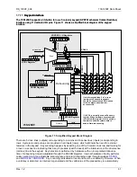
Figure 14 shows how multiple 8010 devices can be connected to the 73S1209F.
73S1209F
73S8010
73S8010
SC3
SC2
73S8010
SC(n)
SC1
INT3
SDA
SCL
INT
SCL
SDA
INT
SCL
SDA
INT
SCL
SDA
SAD(0:2)
SAD(0:2)
SAD(0:2)
I/O
RST
CLK
C4
C8
VPC
PRES
PRES
PRES
IOUC
IOUC
IOUC
XTALIN
XTALIN
XTALIN
GND
PRES
VPC
PRES
SIO
SCLK
VCC
Figure 14: External Smart Card Interface Block Diagram


