


73S1209F Data Sheet
DS_1209F_004
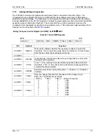
Serial Interface 0 Control Register (S0CON): 0x9B
Å
0x00
Transmit and receive data are transferred via this register.
Table 38: The S0CON Register
MSB LSB
SM0 SM1 SM20
REN0
TB80 RB80 TI0 RI0
Bit Symbol
Function
S0CON.7
SM0
These two bits set the UART0 mode:
Mode Description
SM0 SM1
0 N/A 0 0
1 8-bit
UART 0
1
2 9-bit
UART 1
0
3 9-bit
UART 1
1
S0CON.6 SM1
S0CON.5
SM20
Enables the inter-processor communication feature.
S0CON.4
REN0
If set, enables serial reception. Cleared by software to disable reception.
S0CON.3
TB80
The 9th transmitted data bit in Modes 2 and 3. Set or cleared by the MPU,
depending on the function it performs (parity check, multiprocessor
communication etc.).
S0CON.2
RB80
In Modes 2 and 3 it is the 9th data bit received. In Mode 1, if SM20 is 0,
RB80 is the stop bit. In Mode 0 this bit is not used. Must be cleared by
software.
S0CON.1
TI0
Transmit interrupt flag, set by hardware after completion of a serial transfer.
Must be cleared by software.
S0CON.0
RI0
Receive interrupt flag, set by hardware after completion of a serial
reception. Must be cleared by software.
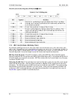
1.7.4.2 Serial
Interface
1
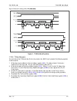
The Serial Interface 1 can operate in 2 modes:
•
Mode A
This mode is similar to Mode 2 and 3 of Serial interface 0, 11 bits are transmitted or received: a start
bit (0), 8 data bits (LSB first), a programmable 9th bit, and a stop bit (1). The 9th bit can be used to
control the parity of the serial interface: at transmission, bit TB81 in
is outputted as the 9th
bit, and at receive, the 9th bit affects RB81 in Special Function Register
. The only difference
between Mode 3 and A is that in Mode A only the internal baud rate generator can be use to specify
baud rate.
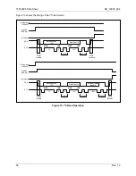
•
Mode B
This mode is similar to Mode 1 of Serial interface 0. Pin RX serves as input, and TX serves as serial
output. No external shift clock is used, 10 bits are transmitted: a start bit (always 0), 8 data bits (LSB
first), and a stop bit (always 1). On receive, a start bit synchronizes the transmission, 8 data bits are
available by reading
, and stop bit sets the flag RB81 in the Special Function Register
. In mode 1, the internal baud rate generator is use to specify the baud rate.
register is used to read/write data to/from the serial 1 interface.
42
Rev.
1.2


