


DS_1209F_004
73S1209F Data Sheet
Rev. 1.2
37
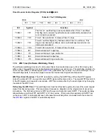
Table 26: Control Bits for External Interrupts
Enable Bit Description
Flag Bit
Description
EX0
Enable external interrupt 0
IE0
External interrupt 0 flag
EX1
Enable external interrupt 1
IE1
External interrupt 1 flag
EX2
Enable external interrupt 2
IEX2
External interrupt 2 flag
EX3
Enable external interrupt 3
IEX3
External interrupt 3 flag
EX4
Enable external interrupt 4
IEX4
External interrupt 4 flag
EX5
Enable external interrupt 5
IEX5
External interrupt 5 flag
EX6
Enable external interrupt 6
IEX6
External interrupt 6 flag
1.7.3.4
Power Down Interrupt Logic
The 73S1209F contains special interrupt logic to allow INT0 to wake up the CPU from a power down
(CPU STOP) state. See the
section for details.
1.7.3.5
Interrupt Priority Level Structure
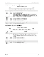
All interrupt sources are combined in groups, as shown in Table 27.
Table 27: Priority Level Groups
Group
0
External interrupt 0
Serial channel 1 interrupt
1
Timer 0 interrupt
–
External interrupt 2
2
External interrupt 1
–
External interrupt 3
3
Timer 1 interrupt
–
External interrupt 4
4
Serial channel 0 interrupt
–
External interrupt 5
5
–
–
External interrupt 6
Each group of interrupt sources can be programmed individually to one of four priority levels by setting or
clearing one bit in the special function register
. If requests of the same priority level
are received simultaneously, an internal polling sequence as per Table 31 determines which request is
serviced first.
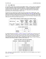
IEN enable bits must be set to permit any of these interrupts to occur. Likewise, each interrupt has its
own flag bit that is set by the interrupt hardware.
Interrupt Priority 0 Register (IP0): 0xA9
Å
0x00
Table 28: The IP0 Register
MSB LSB
– WDTS IP0.5 IP0.4 IP0.3 IP0.2 IP0.1 IP0.0
Note: WDTS is not used for interrupt controls.