


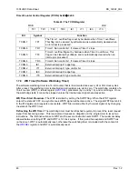


73S1209F Data Sheet
DS_1209F_004
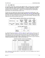
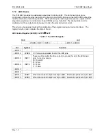
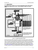
1.7.10 I
2
C Master Interface
The 73S1209F includes a dedicated fast mode, 400kHz I
2
C Master interface. The I
2
C interface can read
or write 1 or 2 bytes of data per data transfer frame. The MPU communicates with the interface through
six dedicated SFR registers:
•
Device Address (
)
•
)
•
)
•
Read Data (
•
Secondary Read Data (
•
Control and Status
(
)
register is used to set up the slave address and specify if the transaction is a read or write
register sets up, starts the transaction and reports any errors that may occur. When
the I
2
C transaction is complete, the I
2
C interrupt is reported via external interrupt 6. The I
2
C interrupt is
automatically de-asserted when a subsequent I
2
C transaction is started. The I
2
C interface uses a 400kHz
clock from the time-base circuits.
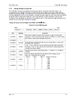
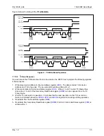
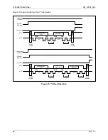
1.7.10.1 I
2
C Write Sequence
To write data on the I
2
C Master Bus, the 80515 has to program the following registers according to the
following sequence:
1. Write slave device address to Device Address register (
). The data contains 7 bits for the slave
device address and 1 bit of op-code. The op-code bit should be written with a 0 to indicate a write
operation.
2. Write data to Write Data register (
). This data will be transferred to the slave device.
3. If writing 2 bytes, set bit 0 of the Control and Status register (
) and load the second data byte to
Secondary Write Data register (
4. Set bit 1 of the
2
C Master Bus.
5. Wait for I
2
C interrupt to be asserted. It indicates that the write on I
2
C Master Bus is done. Refer to
register for masking and flag operation.
54
Rev.
1.2


