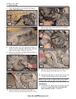
7.
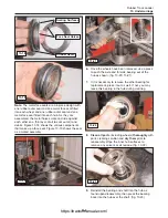
Remove the snap ring securing the bearing
assembly to the outer sprocket shaft. (fig. 11-24)
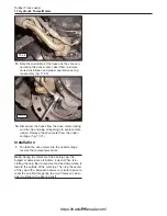
8.
Use a jaw style puller and an impact wrench to
remove the bearing assembly from the sprocket
shaft. (fig. 11-25)
9.
Remove the bolts securing the sprocket to the
drive motor. (fig. 11-26)
10.
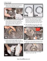
Remove the sprocket assembly from the undercar-
riage. (fig. 11-27)
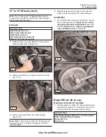
11.
Remove the bolts securing the drive motor to the
drive table. (fig. 11-28)
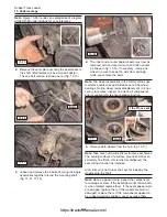
12.
Lift the drive motor straight upward until it clears
the drive table, then forward to expose the
hydraulic hoses for removal. (fig. 11-29)
Note:
There are two large bolts near the front of the
drive motor support securing it to the lower drive table
from the inside (near the chassis). Remove these bolts
prior to lifting the motor to provide additional clearance
for the hoses as you lift the motor upward. (fig. 11-29)
11-7
Rubber Track Loader
11. Hydraulic Pumps/Motors
11-24
11-25
11-26
11-27
11-28
11-29
Remove Bolts
https://tractormanualz.com/
Содержание ASV SR70
Страница 5: ...IV https tractormanualz com...
Страница 11: ...1 6 https tractormanualz com...
Страница 41: ...4 20 https tractormanualz com...
Страница 87: ...12 8 https tractormanualz com...
Страница 105: ...14 6 https tractormanualz com...
Страница 109: ...15 4 https tractormanualz com...
Страница 125: ...16 16 https tractormanualz com...
Страница 133: ...17 8 https tractormanualz com...
Страница 137: ...18 4 https tractormanualz com...
Страница 139: ...19 2 https tractormanualz com...


