Tilt-Up Cab
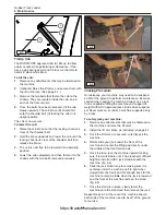
The ROPS/FOPS approved cab (A) tilts up to allow
easier access while performing maintenance. It fea-
tures a gas spring assist and a brace mechanism to
hold it in place while tilted.
To tilt the cab:
1.
Remove any attachments that may be fastened to
the machine.
2.
(Optional) Raise the lift arms and secure them with
the lift arm brace. (See page 4-1.)
3.
Remove the two bolts that fasten the cab to the
chassis. They are located inside the cab, one in
each of the front corners.
4.
Once the bolts have been removed, tilt the cab
slowly upwards. The cab brace (B) should fall
onto the shoulder bolt (C) locking the cab in its
upright position.
The cab is now secure.
To lower the cab:
1.
Raise the cab brace so that the locking channel is
clear of the shoulder bolt.
2.
Hold the brace upwards and lower the cab until the
locking channel is clear of the shoulder bolt then
release the brace.
3.
The cab is now free to be lowered into operating
position.
4.
Lower the cab completely and then fasten it to the
chassis with the two bolts removed previously.
Jacking Procedure
Occasionally, your machine may need to be suspend-
ed off of the ground to perform maintenance. Exercise
caution when jacking the machine. Always use a jack
that is capable of lifting the machine and support its
weight with ASV approved jack stands while suspend-
ed. Never work on or under a machine supported only
by a jack.
To safely jack your machine:
1.
Remove any attachments that may be fastened to
the machine and raise the lift arms.
2.
Install the lift arm brace as instructed on page 4-1.
3.
Once the lift arms are secured, carefully exit the
machine.
4.
Roll or slide your jack under the front of the
machine and center the lifting pad directly under
the middle of the front torsion axle.
5.
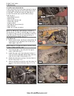
Once in place, jack the machine upward making
sure it remains stable until it has reached sufficient
height to install an ASV jack stand beneath the
machine. (fig. 4-4)
6.
Slide the jack stand into place making sure it is
centered under the machine (left to right when
viewed from the front) and far enough back for the
machine to remain stable when the jack is lowered
and the front of the machine rests on the stand.
(fig. 4-5)
7.
Once the stand is in place, slowly lower the
machine onto the stand and then remove the jack.
Repeat steps 4-7 at the rear of the machine should
both ends of the machine need to be off of the ground
for service.
4-2
Rubber Track Loader
4. Maintenance
B
C
4-3
4-4
4-5
A
https://tractormanualz.com/
Содержание ASV SR70
Страница 5: ...IV https tractormanualz com...
Страница 11: ...1 6 https tractormanualz com...
Страница 41: ...4 20 https tractormanualz com...
Страница 87: ...12 8 https tractormanualz com...
Страница 105: ...14 6 https tractormanualz com...
Страница 109: ...15 4 https tractormanualz com...
Страница 125: ...16 16 https tractormanualz com...
Страница 133: ...17 8 https tractormanualz com...
Страница 137: ...18 4 https tractormanualz com...
Страница 139: ...19 2 https tractormanualz com...


