6.
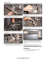
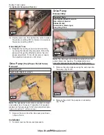
Once the snap rings and retainers are removed,
slide the piston assemblies out one at a time and
inspect them for damage. (fig. 16-39, 16-40)
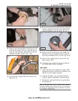
Note:
While inspecting the piston assemblies, pay
close attention to the piston ring. Look for any signs of
damage or cracking. (fig. 16-40)
7.
Inspect the rollers and sleeves as well to make
sure there are no scratches or other damage that
may affect operation.
Assembly
1.
Replace worn or damaged components, thorough-
ly clean all parts, then reassemble the motor by
reversing the disassembly procedure.
Drive Pump
(Drive Relief Valves)
Disassembly & Adjustment
1.
With machine off and cool and with hydraulic actu-
ators relaxed, remove the drive pump from the
machine by following the procedure in section 11.
2.
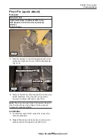
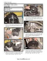
Remove the drive pressure relief valves as shown
in fig. 16-42 and 16-43.
3.
If adjustment is needed (see drive pressure check
procedure in section 17), loosen the allen type set
screw on the valve.
16-9
Rubber Track Loader
16. Hydraulic Component Service
16-39
16-40
Ring
16-41
Ring Groove
Required Tools
Allen Wrench/Socket
Combination/Socket wrench
16-42
16-43
16-44
https://tractormanualz.com/
Содержание ASV SR70
Страница 5: ...IV https tractormanualz com...
Страница 11: ...1 6 https tractormanualz com...
Страница 41: ...4 20 https tractormanualz com...
Страница 87: ...12 8 https tractormanualz com...
Страница 105: ...14 6 https tractormanualz com...
Страница 109: ...15 4 https tractormanualz com...
Страница 125: ...16 16 https tractormanualz com...
Страница 133: ...17 8 https tractormanualz com...
Страница 137: ...18 4 https tractormanualz com...
Страница 139: ...19 2 https tractormanualz com...


