


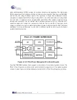


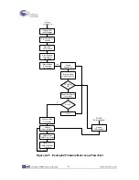

6.
On the PSoC Power Management EBK board, make sure the power jumper (J5) is set to “EXT”.
Note that this is not the default setting for the J5 jumper.
7.
Apply 12 VDC power to the PSoC Power Management EBK using J3
8.
Re-attach the USB cable from the PC to the PSoC 3 DVK Program/Debug USB port (use J1 -
the USB connector closest to the corner of the board)
9.
If the PME EBK cannot be detected by PSoC, status debug messages will be displayed on the
LCD to assist with rectifying the problem
10.
Going forward, every time PSoC is re-programmed, press the Reset (SW1) button on the PSoC
3 DVK to run the newly programmed firmware image
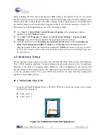
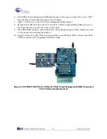
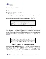
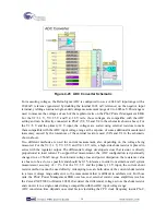
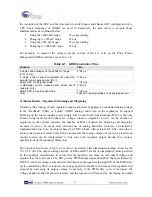
Figure 4-9 CY8CKIT-030 PSoC 3 DVK with PSoC Power Management EBK Connected
to Port E (Running Example 2)
19
Содержание CY8CKIT-035
Страница 1: ......
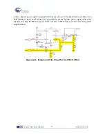
Страница 38: ...Chapter 5 Schematics 5 1 Primary 12V Power Input 37 ...
Страница 39: ...5 2 DVK Connector and Debug Test Points 5 3 Voltage Regulator V1 5V 38 ...
Страница 40: ...5 4 Voltage Regulator V2 3 3V 5 5 Voltage Regulator V3 2 5V 5 6 Voltage Regulator V4 1 8V 39 ...
Страница 41: ...5 7 I2C SMBus PMBus Interface Connector 5 8 Layout 5 8 1 Top Layer 40 ...
Страница 42: ...5 8 2 Ground Layer 5 8 3 Power Layer 41 ...
Страница 43: ...5 8 4 Bottom Layer 42 ...
Страница 44: ...5 8 5 Top Silkscreen 43 ...