Chapter 3
PME EBK Hardware Overview
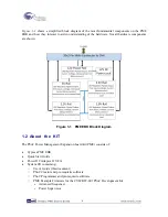
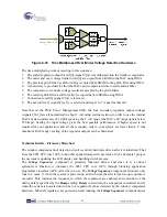
Figure 3-1 PME Hardware Components
The Power Management EBK Board consists of a 12V primary input power source and 4 secondary
voltage rails: V1=5V, V2=3.3V, V3=2.5V and V4=1.8V. Voltage rail V1 feeds power to the other
three rails V2, V3 and V4. Therefore, disabling V1 will disable V2-V4 as a result. Each secondary
rail consists of a regulator with enable input, circuitry that enables PSoC to apply a DC control
voltage to the regulator feedback or adjust pin, as well as fixed and adjustable (potentiometer) load
elements. Two jumpers are provided for each rail to (1) disconnect all loads or (2) disconnect only
the adjustable load.
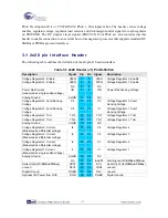
PME EBK provides an I2C/SMBus/PMBus connector. A 40-pin (2×20) header J1 is provided to
interface this board with the host PSoC on a development kit platform such as the CY8CKIT-001
10
Содержание CY8CKIT-035
Страница 1: ......
Страница 38: ...Chapter 5 Schematics 5 1 Primary 12V Power Input 37 ...
Страница 39: ...5 2 DVK Connector and Debug Test Points 5 3 Voltage Regulator V1 5V 38 ...
Страница 40: ...5 4 Voltage Regulator V2 3 3V 5 5 Voltage Regulator V3 2 5V 5 6 Voltage Regulator V4 1 8V 39 ...
Страница 41: ...5 7 I2C SMBus PMBus Interface Connector 5 8 Layout 5 8 1 Top Layer 40 ...
Страница 42: ...5 8 2 Ground Layer 5 8 3 Power Layer 41 ...
Страница 43: ...5 8 4 Bottom Layer 42 ...
Страница 44: ...5 8 5 Top Silkscreen 43 ...


