background image

MAINTENANCE

EZ Rider 330730 (12--01)

64

BRAKES AND TIRES

BRAKES

The mechanical brake is located on the front

wheel. The

brake

is operated by the

brake pedal

.

Check the brake adjustment after every 200 hours

of operation. If the brake does not respond well to

pressure on the brake pedal, you may need to

adjust the brake.

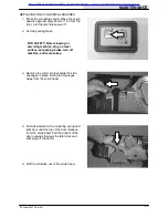
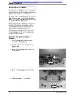
BRAKE ADJUSTMENT:
Remove the cotter key from the brake extension

arm, and position the extension arm in the next

adjustment hole in the brake link.

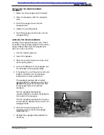
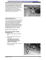
Insert the cotter key back into the brake extension

arm, and check the brake for proper operation.

New & Reconditioned Equipment & Parts - www.southeasternequipment.net

Содержание EZ Rider

Страница 1: ...330730 Rev 03 330730 EZ Ridert t t t Operator Manual New Reconditioned Equipment Parts www southeasternequipment net ...

Страница 2: ...provide excellent service However the best results will be obtained at minimum costs if D The machine is operated with reasonable care D The machine is maintained regularly per the maintenance instructions provided D The machine is maintained with TENNANT supplied or equivalent parts Manual Number 330730 Revision 03 Published 6 02 Copyright E 2000 2002 TENNANT Printed in U S A New Reconditioned Eq...

Страница 3: ...E CHART 37 LUBRICATION 38 STEERING CASTER PIVOT BEARING 38 REAR SQUEEGEE CASTERS 38 STEERING GEAR CHAIN 38 Page BATTERIES 39 CHARGING THE BATTERIES 41 SELF DIAGNOSTIC TEST 43 ELECTRIC MOTORS 44 SCRUB BRUSHES AND PADS 44 DISK BRUSHES 44 REPLACING THE DISK BRUSHES OR PADS 45 CYLINDRICAL BRUSHES 48 CHECKING AND ADJUSTING CYLINDRICAL BRUSH PATTERN 48 REPLACING THE CYLINDRICAL BRUSHES 51 SOLUTION SYSTE...

Страница 4: ...ACHINE 66 TRANSPORTING THE MACHINE 66 MACHINE JACKING 68 STORAGE INFORMATION 69 FREEZE PROTECTION 69 SPECIFICATIONS 70 GENERAL MACHINE DIMENSIONS CAPACITIES 70 GENERAL MACHINE PERFORMANCE 70 POWER TYPE 71 TIRES 71 MACHINE DIMENSIONS 72 INDEX 73 New Reconditioned Equipment Parts www southeasternequipment net ...

Страница 5: ...tarting machine Make sure all safety devices are in place and operate properly Check brakes and steering for proper operation if so equipped 3 When starting machine Keep foot on brake and directional lever in neutral if so equipped 4 When using machine Use brakes to stop machine if so equipped Go slow on inclines and slippery surfaces Use care when reversing machine Do not carry riders on machine ...

Страница 6: ...ew label in its place BATTERY CHARGING LABEL LOCATED ON AND UNDERNEATH THE SEAT SUPPORT FLAMMABLE SPILLS LABEL LOCATED ON THE SEAT SUPPORT FOR SAFETY LABEL LOCATED ON THE SEAT SUPPORT FLAMMABLE MATERIALS LABEL LOCATED ON THE UNDERSIDE OF THE TANK COVER AND ON THE LEFT SIDE OF THE OPERATOR COMPARTMENT 353451 New Reconditioned Equipment Parts www southeasternequipment net ...

Страница 7: ...ting this machine FOR SAFETY Do not operate machine unless operation manual is read and understood Check the machine for shipping damage Check to make sure machine is complete per shipping instructions Keep your machine regularly maintained by following the maintenance information in this manual We recommend taking advantage of a regularly scheduled service contract from your TENNANT representativ...

Страница 8: ...I J J G K F H L G F I K A Solution tank B Tank Cover C Vacuum fan inlet screen D Steering wheel E Recovery tank F Operator seat G Batteries H Scrub head I Side squeegee J Rear wheel K Rear squeegee L Front wheel New Reconditioned Equipment Parts www southeasternequipment net ...

Страница 9: ...ey switch Circuit breaker 1 Battery charge Circuit breaker 2 Scrubbing Circuit breaker 3 Squeegee Circuit breaker 4 Brush pressure Circuit breaker 5 Recovery tank full Circuit breaker 6 Solution flow Circuit breaker 7 Circuit breaker 8 Circuit breaker 9 New Reconditioned Equipment Parts www southeasternequipment net ...

Страница 10: ...egee switch D Hourmeter E Power kill switch F On Off key switch G Horn button H Solution flow lever I Directional pedal J Brake pedal K Parking brake pedal L Operator seat M Recovery tank full indicator N Circuit breaker panel O Battery discharge indicator P Scrub switch New Reconditioned Equipment Parts www southeasternequipment net ...

Страница 11: ...lace FOR SAFETY Before leaving or servicing machine stop on level surface set parking brake turn off machine and remove key Release Press the brake pedal to unlock the parking brake pedal DIRECTIONAL PEDAL The directional pedal controls direction of travel and the propelling speed of the machine You change the speed of the machine with the pressure of your foot the harder you press the faster the ...

Страница 12: ...on the rear squeegee will automatically raise After a short delay the vacuum will stop Neutral Take your foot off the directional pedal and it will return to the neutral position When the directional pedal returns to the neutral position the scrub brushes will stop and after a short delay the scrub head will raise STEERING WHEEL The steering wheel controls the machine s direction of travel Left Tu...

Страница 13: ...l switch halts all power to the machine Stop machine power Press the power kill switch Restart machine power Turn off the machine with the on off switch Turn the power kill switch to the right to release the switch Turn on the machine with the on off key switch HOURMETER The hourmeter records the number of hours the machine has been operated Check the hourmeter regularly this information is used t...

Страница 14: ...indicators display the pressure selection The brush pressure indicator has three positions Brush pressure increases as the indicator light moves to the right across the display Travel speed and floor conditions will affect the scrubbing performance Under normal conditions the brush pressure should be set in one of the minimum settings Set the brush pressure in the maximum setting to scrub a heavil...

Страница 15: ... the switch will go off There will be a slight delay before the vacuum shuts off NOTE The rear squeegee lowers and the scrubbing vacuum starts automatically when the scrubbing operations start NOTE The rear squeegee will raise and the scrubbing vacuum will shut off after a short delay when the machine travels in reverse NOTE The rear squeegee will raise and the scrubbing vacuum fan will shut off a...

Страница 16: ...e the batteries more often than is necessary to prolong the life of the batteries Do not charge the batteries with a top off charge if there is enough remaining charge in the batteries for the next machine use Discharge the batteries to a 20 level when the battery discharge indicator segments shut off before fully charging the batteries Do not allow the batteries to become completely discharged as...

Страница 17: ... operator console The chart below shows the circuit breakers and the electrical components they protect Circuit Breaker Rating Circuit Protected CB1 5 A Machine power CB2 10 A Lights CB3 10 A Horn CB4 10 A Back up alarm CB5 10 A Control panel CB6 20 A Vacuum fan CB7 25 A Left brush motor CB8 25 A Right brush motor FUSE The fuse is a one time protection device designed to stop the flow of current i...

Страница 18: ...ction SEAT SUPPORT ARM The seat support arm holds the seat up to allow access to the batteries The support arm automatically engages when the seat is lifted all the way up Lower the seat support by slightly raising it while pushing the seat support arm inward SQUEEGEE WHEEL CAMS The squeegee wheel cams adjust the squeegee deflection along the entire length of the squeegee There are wheel cams at e...

Страница 19: ...nd recovery tank Water and detergent from the solution tank flow to the floor through a solution valve The brushes use the detergent and water solution to scrub the floor clean As the machine propels forward the squeegee wipes the dirty solution from the floor The suction created by the vacuum fan then draws the dirty solution from the squeegee into the recovery tank The steering wheel controls th...

Страница 20: ...CKLIST Perform the following steps before operating the machine Check under the machine for leaks Check the brakes and steering for proper operation Check the squeegees for wear and damage New Reconditioned Equipment Parts www southeasternequipment net ...

Страница 21: ...th the parking brake set FOR SAFETY When starting machine keep foot on brake and directional pedal in neutral 2 Turn the machine power on 3 Release the machine parking brake 4 Drive the machine to the area to be cleaned NOTE The machine will not travel unless the operator is sitting in the operator s seat New Reconditioned Equipment Parts www southeasternequipment net ...

Страница 22: ...n brake and directional pedal in neutral 2 Drive the machine to the tank filling site 3 Turn the machine power off See the STOP THE MACHINE section of the manual 4 Set the machine parking brake FOR SAFETY Before leaving or servicing machine stop on level surface set parking brake turn off machine and remove key New Reconditioned Equipment Parts www southeasternequipment net ...

Страница 23: ...e of soilage and brush pressure all play an important role in determining the type and concentration of detergent to be used For specific recommendations contact your Tennant representative WARNING Flammable materials can cause an explosion or fire Do not use flammable materials in tank s FOR SAFETY When using machine follow mixing and handling instructions on chemical containers 6 Lower the tank ...

Страница 24: ...sle and scrub your way out Adjust the machine speed scrub brush pressure and solution flow as required when scrubbing Use minimum scrub brush pressure and solution flow required for the best results If you see poor scrubbing performance stop scrubbing and refer to MACHINE TROUBLESHOOTING For best results use the correct brush type for your cleaning application The following are recommended brush a...

Страница 25: ...gh gloss Use for buffing very soft finishes and lower traffic areas or use for polishing soft waxes on wood floors Cylindrical polypropylene scrub brush This cylindrical brush uses a softer general purpose polypropylene bristle to lift lightly compacted soilage without scuffing high gloss coated floors Cylindrical nylon scrub brush This cylindrical brush is recommended for scrubbing coated floors ...

Страница 26: ...rations See the SCRUB SWITCH section of the manual WARNING Flammable materials or reactive metals can cause explosion or fire Do not pick up 4 Adjust the solution flow as needed Increase flow Push the solution flow lever forward Use this flow rate for rough floors and heavy or compacted dirt Decrease flow Pull the solution flow lever back Use this flow rate for smooth floors and light dirt Stop fl...

Страница 27: ...E If an excess of water in the recovery tank triggers an overflow switch the recovery tank full indicator will light on the control panel All scrubbing functions will be cancelled To turn the indicator light off drain the recovery tank then press the scrub switch NOTE A low battery and a no brush current sensed will also cancel the scrub system 5 Adjust brush pressure for cleaning application See ...

Страница 28: ...ximum solution flow setting and a higher brush pressure setting Let the solution remain on the floor for 10 to 15 minutes then make a second scrubbing pass with the rear and side squeegees down FOR SAFETY When using machine go slow on inclines and slippery surfaces OPERATION ON INCLINES Drive the machine slowly on inclines FOR SAFETY When using machine go slow on inclines and slippery surfaces The...

Страница 29: ...ll stop and after a short delay the rear squeegee will automatically raise and the scrubbing vacuum fan will stop Continue driving the machine forward until the rear squeegee raises and the vacuum fan shuts off 2 When the vacuum fan stops take your foot off the directional pedal 3 Press the brake pedal to stop the machine New Reconditioned Equipment Parts www southeasternequipment net ...

Страница 30: ...section of the manual 2 Drive the machine next to an appropriate disposal site 3 Turn the machine power off See the STOP THE MACHINE section of the manual FOR SAFETY Before leaving or servicing machine stop on level surface and turn off machine 4 Set the machine parking brake FOR SAFETY Before leaving or servicing machine stop on level surface set parking brake turn off machine and remove key 5 Li...

Страница 31: ... NOT use steam to clean the tanks Excessive heat can damage the tanks and components WARNING Flammable materials can cause an explosion or fire Do not use flammable materials in tank s 8 Check the vacuum fan inlet filter daily Clean inlet filter with a damp cloth or hose when dirty Allow filter to dry completely before replacing it into machine New Reconditioned Equipment Parts www southeasternequ...

Страница 32: ... side squeegee in place on the right hand side of the machine Swing the squeegee away from the scrub head 11 Cylindrical scrub head Remove and clean the debris trough Place the trough back in the scrub head when clean NOTE The scrub head must be lowered approximately 25 mm 1 in to remove debris trough New Reconditioned Equipment Parts www southeasternequipment net ...

Страница 33: ...our foot off the directional pedal Step on the brake predal to stop the machine 3 Turn the machine power off 4 Set the machine parking brake FOR SAFETY Before leaving or servicing machine stop on level surface set parking brake turn off machine and remove key New Reconditioned Equipment Parts www southeasternequipment net ...

Страница 34: ...reading the charge level of the batteries Check for wire string or twine wrapped around the scrub brushes Check the squeegees for wear or damage Check the squeegee suction hose for obstructions Cylindrical brushes Empty and clean the debris tray Drain and clean the recovery tank Check under the machine for leaks Check the service records to determine maintenance requirements New Reconditioned Equi...

Страница 35: ...e parking brake and turn the machine power off FOR SAFETY Before leaving or servicing machine stop on level surface set parking brake turn off machine and remove key 3 Connect the QuickMopt attachment to the mounting bracket on the front of the machine 4 Fasten the latches on the front of the mountng bracket Release the parking brake and drive to the designated area to be swept New Reconditioned E...

Страница 36: ...the QuickMopt 6 Turn the vacuum and brushes on lower brushes and begin scrubbing 7 Remove and refasten the QuickMopt head covers with the easy to remove snaps Remove the head covers to rotate shake and clean at regular intervals New Reconditioned Equipment Parts www southeasternequipment net ...

Страница 37: ...er tripped Reset circuit breaker Little or no solution flow to the floor Solution tank empty Fill solution tank Solution control rod broken or out of adjustment Replace and or adjust rod Solution flow turned off Turn solution flow on Solution supply lines plugged Flush solution supply lines Solution solenoid clogged or stuck Clean or replace Poor scrubbing performance Debris caught on scrub brushe...

Страница 38: ...MAINTENANCE EZ Rider 330730 9 00 36 MAINTENANCE 1 1 2 8 7 9 11 5 10 4 3 6 12 12 13 14 14 New Reconditioned Equipment Parts www southeasternequipment net ...

Страница 39: ...k for damage and wear 2 100 Hours 5 Cylindrical scrub brush drive belts Check tension 2 3 Steering caster pivot bear ing Lubricate SPL 1 9 Tank and vacuum fan seals Check for damage and wear 3 14 Tires Check for damage and wear 3 200 Hours 4 Battery terminals and cables HCheck and clean 12 13 Brake Check adjustment 1 6 Steering gear chain Lubricate GL 1 500 Hours 9 Vacuum fan motor Check motor bru...

Страница 40: ...TERS The rear squeegee casters are located on the back side of the rear squeegee Lubricate the pivot point and caster bearing on each squeegee caster with Lubriplate EMB grease TENNANT part no 01433 1 every 50 hours STEERING GEAR CHAIN The steering gear chain is located directly above the front tire Lubricate with SAE 90 weight gear lubricant every 200 hours of use New Reconditioned Equipment Part...

Страница 41: ...o clean the terminal posts and the cable connectors Wipe off all cleaning solution residue After cleaning apply a coating of clear battery post protectant to the terminals and the cable connectors Keep the tops of the batteries clean and dry Objects made of metal can potentially short circuit the batteries Keep all metallic objects off the batteries Replace any worn or damaged wires Check the elec...

Страница 42: ...id are not thoroughly mixed the readings may not be accurate Check the hydrometer readings against the following chart to determine the remaining battery charge level SPECIFIC GRAVITY BATTERY at 27_ C 80_F CHARGE 1 265 100 Charged 1 223 75 Charged 1 185 50 Charged 1 148 25 Charged 1 110 Discharged NOTE If the readings are taken when the battery electrolyte is any temperature other than 27_ C 80_ F...

Страница 43: ...Lift the operator seat to access the batteries The support arm automatically engages when the seat is lifted all the way up 4 Check the water level in all battery cells If the level is low add just enough distilled water to cover the plates DO NOT OVERFILL The batteries can overflow during charging due to expansion NOTE Make sure the battery caps are in place while charging FOR SAFETY When maintai...

Страница 44: ...l start automatically When the batteries are fully charged the TENNANT charger will automatically turn off 8 After the charger has turned off unplug the charger from the battery connector on the machine 9 Reconnect the battery connector to the machine connector FOR SAFETY When maintaining or servicing machine avoid contact with battery acid 10 Check the electrolyte level in each battery cell after...

Страница 45: ...urn on and off D The solution valve turns on and off D The vacuum fan relay is momentarily energized the vacuum fan does not turn on D The brushes turn on and off 4 If the electrical system passes the self diagnostic test the indicator light above the squeegee switch will blink green If the self diagnostic test finds an error in the system the recovery tank full indicator will blink red To determi...

Страница 46: ...nd the brush or brush drive hub Also check for brush damage and wear DISK BRUSHES The disk brushes should be replaced if a large number of bristles are missing or if bristle length is less than 10 mm 0 5 in Cleaning pads must be placed on pad drives before they are ready to use The cleaning pad is held in place by a pad holder Cleaning pads need to be cleaned immediately after using with soap and ...

Страница 47: ... Before leaving or servicing machine stop on level surface set parking brake turn off machine and remove key 3 Remove the cotter pin and washer holding the side squeege in the closed position 4 Open the side squeege 5 Turn the scrub brush pad driver until you can see the brush driver spring clip New Reconditioned Equipment Parts www southeasternequipment net ...

Страница 48: ...rom under the scrub head 7 PAD DRIVER ONLY Turn the pad driver over to access the spring clip underneath 8 Press the spring clip together with your thumb and index finger to remove the center disk 9 Flip or replace the scrub pad center the scrub pad on the pad driver 10 Replace the center disk to secure the pad in place on the driver New Reconditioned Equipment Parts www southeasternequipment net ...

Страница 49: ...ket with the drive plug 13 While pressing the brush spring clip together with your thumb and index finger lift the scrub brush onto the drive plug 14 Check to make sure the brush is securely mounted on the brush drive hub 15 Close the side squeege and secure in place with the washer and cotter key 16 Repeat for the other brush New Reconditioned Equipment Parts www southeasternequipment net ...

Страница 50: ...performance NOTE Fill the solution tank before checking or adjusting the brush pattern CHECKING AND ADJUSTING CYLINDRICAL BRUSH PATTERN 1 Apply chalk or another material that will not easily blow away to a smooth level section of the floor 2 Set the parking brake 3 Lower the scrub head in the chalked area Allow the machine to scrub in the same place for 15 to 20 seconds NOTE If chalk or other mate...

Страница 51: ...ghten the brush pattern A To adjust brush taper push downward on the mounting spring and idler door until the top of the door releases from the scrub head Pull the bottom of the door outward then pull the idler door and idler plug off the brush B While holding the flat end of the idler shaft with a wrench loosen the mounting screw on the outside of the idler door 10355 10356 New Reconditioned Equi...

Страница 52: ...nd readjust as necessary until both patterns are the same 6 If one brush pattern is wider than the other the scrub head needs to be leveled Level the scrub head by turning the scrub head links Both scrub head links should be adjusted equally Check the brush patterns again and readjust as necessary until both patterns are the same 350630 New Reconditioned Equipment Parts www southeasternequipment n...

Страница 53: ...el surface set parking brake turn off machine and remove key 3 Remove the cotter pin that holds the side squeegee in place Swing the squeegee away from the scrub head 4 Push downward on the mounting spring and idler door until the top of the door releases from the scrub head Pull the bottom of the door outward then pull the idler door and idler plug off the brush 5 Pull the old brush out of the sc...

Страница 54: ...he door in the scrub head then pull up on the door to latch it into the spring 9 Repeat for the other brush on the other side of the scrub head NOTE Each side of the scrub head is stamped with a letter The idler door of that side of the scrub head is stamped with the same letter Make sure the letter on the door matches the letter on the scrub head when replacing the doors New Reconditioned Equipme...

Страница 55: ...f the tank cover Check the vacuum fan inlet filter daily Clean inlet filter with a damp cloth or hose when dirty Allow filter to dry completely before replacing it into machine SOLUTION TANK The solution tank holds the cleaning solution If deposits form on the bottom of the tank rinse the tank and with a strong blast of warm water A solution filter is located under the machine near the solution co...

Страница 56: ... for leveling and deflection The deflection and leveling of the squeegee blades should be checked daily or when scrubbing a different type of floor The squeegee assembly can be removed from the squeegee pivot to prevent damage during transport of the machine REMOVING THE REAR SQUEEGEE ASSEMBLY 1 Lower the squeegee to approximately 25 mm 1 in from the floor 2 Turn the machine power off and set the ...

Страница 57: ...parking brake 4 Look at the deflection of the squeegee over the full length of the squeegee blade 5 If the deflection is not the same over the full length of the blade turn the squeegee leveling knob to make adjustments The squeegee leveling knob is located directly behind the squeegee suction hose DO NOT disconnect the suction hose from the squeegee frame when leveling squeegee Turn the squeegee ...

Страница 58: ...ok at the deflection of the squeegee blade The correct amount of deflection is 12 mm 0 50 in for scrubbing smooth floors and 15 mm 0 62 in for rough floors 4 Turn the machine power off 5 To adjust the amount of deflection turn the squeegee deflection cams clockwise to decrease the blade deflection Turn the squeegee deflection cams counter clockwise to increase blade deflection 6 Drive the machine ...

Страница 59: ...ng edges To use them all start with one wiping edge To use the next wiping edge rotate the blade end for end To use the next wiping edge rotate the top edges down bottom edges up To use the last edge rotate the blade end for end Rotate squeegee blades when they become worn half way through the thickness of the blade Replace damaged squeegee blades REPLACING OR ROTATING THE REAR SQUEEGEE BLADE 1 Ma...

Страница 60: ... the rear squeegee blade 6 Insert the rotated or new squeegee blade and then insert the retainer band 7 Tighten the two retainer knobs until the ends of the front and rear squeegee blades touch Do not over tighten New Reconditioned Equipment Parts www southeasternequipment net ...

Страница 61: ...iner plate back and pull out the front squeegee blade of the squeegee frame 7 Insert the rotated or new squeegee blade in the squeegee frame lining up the slots in the blade with the tabs on the retainer plate 8 Push the retainer plate forward Tighten the two outside knobs on top of the squeegee assembly 9 Insert the rear squeegee blade and retainer Tighten the two rear blade retainer knobs until ...

Страница 62: ...se the scrub head 2 Turn the machine power off and set the parking brake FOR SAFETY Before leaving or servicing machine stop on level surface set parking brake turn off machine and remove key 3 Remove the cotter pin clevis pin deflector and the retainer bracket from the side squeegee and slide the squeegee out of the frame 4 Slide a new squeegee blade into the frame 5 Replace the retainer bracket ...

Страница 63: ... prevents the buildup of static electricity in the machine The chain is attached to the machine frame Make sure the chain is always touching the floor STEERING GEAR CHAIN The steering gear chain is located directly above the front tire The steering gear chain tension should be checked after the first 50 hours of operation and every 500 hours thereafter The proper deflection should be 3 to 6 mm 0 1...

Страница 64: ...mage and wear every 50 hours of operation The skirts should clear the floor by 0 to 6 mm when the scrub brushes are new and the scrub head is down VACUUM FAN SEAL The vacuum fan seal is located on top of the vacuum fan under the tank cover Check the seal for damage and wear after every 100 hours of operation New Reconditioned Equipment Parts www southeasternequipment net ...

Страница 65: ...ion tank under the tank cover Check the seal for damage and wear after every 100 hours of operation RECOVERY TANK SEAL The recovery tank seal is located around the filter under the tank cover Check the seal for damage and wear after every 100 hours of operation New Reconditioned Equipment Parts www southeasternequipment net ...

Страница 66: ...ation If the brake does not respond well to pressure on the brake pedal you may need to adjust the brake BRAKE ADJUSTMENT Remove the cotter key from the brake extension arm and position the extension arm in the next adjustment hole in the brake link Insert the cotter key back into the brake extension arm and check the brake for proper operation New Reconditioned Equipment Parts www southeasternequ...

Страница 67: ... The machine has three tires one in front and two in the rear of the machine All three tires are solid rubber Check the tires for damage and wear after every 100 hours of operation New Reconditioned Equipment Parts www southeasternequipment net ...

Страница 68: ...ill support the weight of the machine NOTE Empty the recovery and solution tanks before transporting the machine 2 If the loading surface is not horizontal or is higher than 380 mm from the ground use a winch to load machine If the loading surface is horizontal AND is 380 mm 15 in or less from the ground the machine may be driven onto the truck or trailer 3 To winch the machine onto the truck or t...

Страница 69: ...n the front jack supports The rear tie down locations are on the rear corners of the machine 6 If the loading surface is not horizontal or is higher than 380 mm 15 in from the ground use a winch to unload machine If the loading surface is horizontal AND is 380 mm 15 in or less from the ground the machine may be driven off the truck or trailer FOR SAFETY When unloading machine off truck or trailer ...

Страница 70: ...ind the sweeping assembly FOR SAFETY Before leaving or servicing machine stop on level surface set parking brake FOR SAFETY When servicing machine use a hoist or jack that will support the weight of the machine Jack up the rear of the machine from underneath the rear corners Use a piece of wood between the jack and the frame to distribute the machine weight load FOR SAFETY When servicing machine b...

Страница 71: ...atteries or charge them every three months FREEZE PROTECTION 1 Be sure the solution tank is empty 2 Pour 3 8 L 1 gal of pre mixed automotive type windshield washer solution into the solution tank 3 Turn the machine power on 4 Start the solution flow system to circulate the washer solution through the components 5 The washer solution does not need to be drained from the solution tank New Reconditio...

Страница 72: ...drical brush length for 700 mm 28 in scrub head 700 mm 28 in Squeegee width for 700 mm 28 in scrub head 850 mm 33 5 in Scrubbing path width for 700 mm 28 in scrub head 700 mm 28 in Solution tank capacity 130 L 30 gallons Recovery tank capacity 210 L 30 gallons GVWR 1134 Kg 1285 lbs GENERAL MACHINE PERFORMANCE Item Measure Aisle turnaround width 1840 mm 72 5 in Travel Speed 9 6 Km 6 mph Maximum rat...

Страница 73: ... 36 0 60 0 80 Scrub brush cylindrical 36 0 56 0 75 Vacuum fan 36 0 6 0 8 Vacuum fan 36 0 6 0 8 Propelling 36 1 0 1 34 Propelling 36 1 0 1 34 Type VDC amp Hz Phase VAC Chargers Smart 36 25 60 1 120 36 25 50 1 230 TIRES Location Type Size Front 1 Solid 90 mm wide x 250 mm OD 3 5 in wide x 9 8 in OD Rear 2 Solid 90 mm wide x 310 mm OD 3 5 in wide x 12 3 in OD New Reconditioned Equipment Parts www sou...

Страница 74: ...ATIONS EZ Rider 330730 9 00 72 820 mm 32 25 in 820 mm 32 25 in 28 in scrub 850 mm 33 5 in 1370 mm 54 in 1690 mm 66 5 in 353501 MACHINE DIMENSIONS New Reconditioned Equipment Parts www southeasternequipment net ...

Страница 75: ...ntrol panel 12 Self diagnostic test 43 Symbols 7 Controls Brake pedal 9 Circuit breakers 15 Directional pedal 9 Fuse 15 Hourmeter 11 On off key switch 11 Operation of controls 9 Parking brake pedal 9 Power kill switch 11 Rear squeegee switch 13 Scrub switch 12 Solution flow lever 14 Steering wheel 10 Cylindrical brushes 22 Checking and adjusting brush pattern 48 50 Replacing brushes 51 D Debris tr...

Страница 76: ...rear squeegee blade deflection 56 Adjusting squeegee guide rollers 57 Batteries 39 Checking electrolyte level 41 Belts and chains 61 62 Brush drive belts 61 Charging batteries 41 Checking and adjusting brush pattern 48 50 Cylindrical brushes 48 Disk brushes 44 49 Electric motors 44 Leveling the rear squeegee 55 Lubrication 38 Rear squeegee assembly 54 57 Rear squeegee assembly removal 54 Rear sque...

Страница 77: ...tern 48 50 Brush pressure 12 Checking cylindrical brush pattern 48 50 Cylindrical brushes 48 Replacing 51 Disk brushes 44 Replacing 45 Scrub head floor skirts 62 Scrub pads 46 Scrub switch 12 Brush down pressure indicators 12 Brush pressure settings 12 Scrubbing 24 Brushes 22 Double scrubbing 26 Information 22 Operation on inclines 26 Pads 23 Stop scrubbing 27 29 Seals Recovery tank 63 Solution ta...

Страница 78: ...ring wheel 10 Storage information 69 Freeze protection 69 Switches On off key 11 Power kill switch 11 Rear squeegee 13 Scrub 12 Symbols Control panel 7 T Tanks Draining and cleaning 28 31 Filling the tanks 20 Recovery tank 53 Solution tank 53 Tie down location 67 Tires 64 65 Specifications 71 Towing machine 66 Transporting machine 66 Troubleshooting 35 V Vacuum fan 44 Seal 62 New Reconditioned Equ...

Отзывы: