MAINTENANCE
3Ć35
1186 MM267 (6–94)
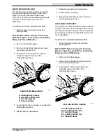
10. Position the stationary cam and the retention
band over the backup strip.
A
B
C
03165
POSITIONING STATIONARY CAM
A. Rear Squeegee Blade
B. Retention Band
C. Stationary Cam
11. Position the levered cam on the squeegee
retention band with the lever down.
A
B
C
00933
INSTALLING LEVERED CAM
A. Rear Squeegee Blade
B. Levered Cam
C. Retention Band
12. Pull the levered cam lever up to tighten the
rear squeegee in place.
NOTE: The cam lever should be above the
horizontal axis to keep from possibly scratching
the floor. If the levered cam is too loose to clamp
the squeegee blade, rotate the stationary cam to
the next flat edge and retighten the levered cam.
Overtightening the levered cam may damage the
squeegee frame and retention band.
TO ADJUST SQUEEGEE
1. Start the engine.
2. Place the squeegee lever in the down
position.
3. Operate the machine in a forward direction
to deflect the squeegee blade.
4. Observe the squeegee blade deflection. The
squeegee blade should be evenly deflected
from one end to the other. If the squeegee
tips are deflecting less than the middle of the
squeegee, turn the squeegee tips adjusting
knob to the right. If the squeegee tips are
deflecting more than the middle of the
squeegee, turn the squeegee tips adjusting
knob to the left. Raise and lower the
squeegee, operate the machine, and
recheck the squeegee tips deflection if an
adjustment was made.
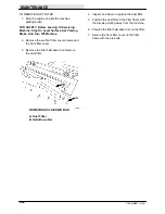
A
B
03166
SQUEEGEE TIPS ADJUSTMENT KNOB
A. Squeegee Tips Adjustment Knob
B. Squeegee Assembly
Содержание 1186
Страница 1: ...1186 MM267 Rev 05 12 95 Operator Manual ...
Страница 8: ...GENERAL INFORMATION 1186 MM267 6 94 vi ...
Страница 10: ...SPECIFICATIONS 1186 MM267 6 94 1Ć2 ...
Страница 14: ...OPERATION 1186 MM267 6 94 2Ć2 ...
Страница 32: ...MAINTENANCE 1186 MM267 6 94 3Ć2 ...
Страница 46: ...MAINTENANCE 1186 MM267 6 94 3Ć16 ELECTRICAL SCHEMATIC 06779 ...
Страница 68: ...APPENDIX 1186 MM267 6 94 4Ć2 ...
Страница 70: ...APPENDIX 1186 MM267 6 94 4Ć4 ...


