- 3 -
3. WIRING
3.1 General
Electrical power wiring must be fitted and certified by
persons with appropriate qualifications and certification.
A signed 'Certificate of Compliance' must be left with the
unit for insurance purposes.
3.2 Power to unit
All power wiring is to be done to the appropriate electrical
standard of the country in which the unit is being installed.
The person installing the wiring is responsible for the
correct selection of wiring size and auxiliary components.
See the Specification Sheet for supply voltage range,
frequency, phase and maximum operating current .
Wire the unit directly from the Electrical Distribution
Board.
The unit should have its own dedicated circuit breaker
on the Distribution Board.
Route the power supply cord
through the entry hole provided.
MWH/R 900: Use the mounting track provided, which
includes cable ties.
DO NOT install wiring in contact with refrigeration piping.
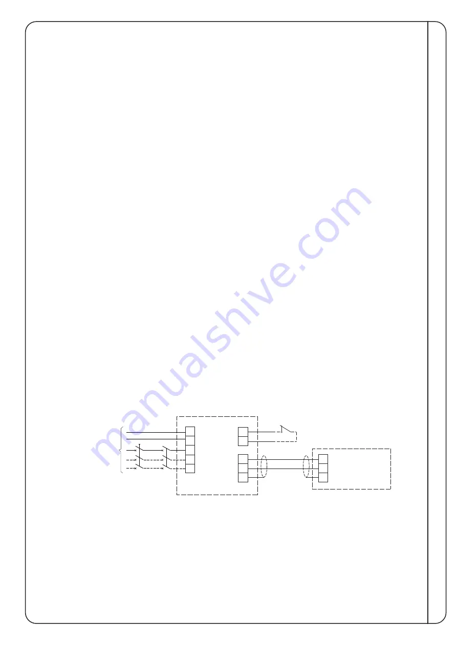
Refer Figure 3 for client wiring.
3.3 Power to optional Room AC Units – ducted type
Single phase mains power wiring to each zoned unit (if
applicable) shall be taken from the distribution board.
3.4 Control
Simply connect power (and water) and switch the unit ON
and the unit's built-in UC8 Controller works to maintain
the default leaving water temperature (LWT) of 45°C.
The maximum LWT can be raised to a maximum of 55°C
if the application requires it, eg long pipe systems and/or
multiple small fan coil units or radiators.
Note: Higher LWT will reduce the efficiency of the unit.
To adjust the supply water temperature, refer
Commissioning 4.3.
MWR only:
In cooling mode, the UC8 works to maintain the default
leaving water temperature (LWT) of 7°C. The minimum
LWT can be lowered to a minimum of 3°C if the
application requires it.
Note: Lower LWT will reduce the efficiency of the unit.
Adding glycol to the water loop is recommended for low
LWT applications.
A single load Leaving Air Temperature (LAT) control
application requires a Programmed Logic Controller
(PLC) to be installed. Refer Temperzone for
'LAT Control
User Guide' for set-up.
MWH 900/2000 models include a PLC for stage control
of more than one compressor, and de-ice control
management.
3.5 BMS Control
MWH/R external control options are limited to Remote
On/Off and Modbus/RTU control using the on-board UC8
(refer Appendix I).
MWH/R 250, 450 Single Compressor models:
An optional PLC is available to enable more options
including BACnet and scheduling. Refer to Temperzone
for more information.
MWH 900/2000 Multiple Compressor models:
PLC supplied as standard and includes BACnet and
scheduling. Refer to Temperzone for more information.
WIRING
Figure 3 Client Wiring
MWH/R Unit
UC8
UC8
E
N
L1
L2
L3
Power Supply
1Ø (2 core+E)
or
3Ø (4 core+E)
depending on unit
External
Protection
Isolator
On
0V
Optional
Remote On/Off
(remove link if used)
Optional
Communicating
BMS Controller
Modbus RTU
B1
A1
0V
B
A
REF
Control
- shielded
twisted pair
2 core + screen
link


