ES
13
Setting
Description
Splicing
his option allows you to access the spli-
cing register to check the values of each
splicing operation .
The fusion splicer allows registering up
to 5,000 splicing operations . You can
download the data with the “OptionFi-
berFusing .exe” programme .
Delete Reg.
This option allows you to delete all the
existing registers .
Saved Images
This option allows you to access the
register containing the saved fusion
images . You can download these ima-
ges with the “OptionFiberFusing .exe”
Delete image
This option allows you to delete all the
existing fusion images .
4.5 Maintenance
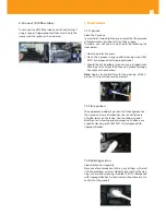
This option allows you to tune the fusion splicer, adjusting
the values shown in the image below:
4.6.1 Electrode stabilisation.
This menu should be executed whenever the electrodes
are replaced or cleaned . The fusion arc produced by the
equipment will thus be stable and constant .
To carry out this process you only need to access the “Electr .
Stab .” menu, push the
, button , wait until the equip-
ment completes at least 5 test arcs, and push the button
again to stop the process . To quit this menu, push the
button .
4.6.2 Sensor values
This menu allows you to display the values of the sensors
included in the equipment .
Internal temperature
Pressure
Oven temperature
DC Voltage
Elevation
Time
4.6.3 Dust test
This menu allows you to check whether cleaning the lenses
is required
4.6.4 Arc calibration.
You should perform an arc calibration whenever you detect
that splicing operations result in an incorrect finish or were
not actually performed . This action will help the fusion spli-
cer automatically adjust the arc power, based on the envi-
ronmental variables (temperature, atmospheric pressure,
etc .) and the type of fibre used (despite all fibre types being
manufactured to a standard, you must take the tolerances
into account) .
Arc calibration procedure:
1
To perform the arc calibration, you need to have pre-
viously selected on "Splicing mode“ the fibre type you
wish to calibrate the splicer for .
2
Once the fibre selected, access the “ARC Calibr ." menu .
3
Strip, clean and cut 2 fibres, just as if you were going to
perform a fusion, and introduce them into the splicer .
4
Close the splicer cover and push
.
5
Fibres will align and the calibration process will start .
6
Once the process completed, the splicer will display “Co-
rrect Cal .” if the calibration was successful . Conversely, if
the splicer displays “Cal . Failed”, you will have to repeat
the process until the splicer displays “Correct Cal .” .
4.6.5 Engine
This menu allows you to readjust the 6 splicer engines
to provide correct fibre alignment and focus (core) . You
should always execute this function if you find any of the
following problems when introducing the fibres into the
fusion splicer:
Fibres with different heights on the LCD screen (not alig-
ned) .
I ncorrect thickness of the fibre core (too thick) .
After accessing the menu, you need to enter the “AA- AAA-
AAA” password to get the process started . Once there, you
will have to select the different engines one by one (
button) to perform the different adjustments (
buttons) until you achieve a perfect alignment and fo-
cus .
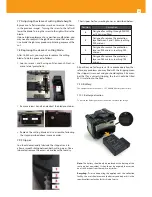
Engines
Description
Left engine
This option allows you to modify the posi-
tion of the left fibre (from left to right for
the X and Y axes, and from top to bottom
for the Y axis) .
Right engine
This option allows you to modify the posi-
tion of the right fibre (from right to left for
the X and Y axes, and from top to bottom
for the X axis) .
Focus
engine-A
This option allows you to adjust the vision
of the fibre (core) on the X axis .
Focus
engine-B
This option allows you to adjust the vision
of the fibre (core) on the Y axis .


