background image

INDEX

70                                                                  OMEGA Installation, Operation, and Maintenance Manual

finding a suitable location, 14
hardware features, 13
input voltage source connection, 18
installation, 15
mounting instructions, 16
operation, 22
power-up, 21
specifications, 62

OMEGA configuration program

changing the cellular telephone SID, 43
changing the login password, 43
exiting, 44
getting started, 40
prerequisites, 39
programming a telephone number, 42
reading the cellular telephone signal, 41

Operation, 22, 31

P

Password

changing, 43

Power supply, 33
Power-up, 21
Prerequisites for OMEGA configuration program, 39
Programming a telephone number, 42

R

Reading the cellular telephone signal, 41
RMA, 65

S

Second dial tone method, 59
Selecting an external antenna, 48

SID

changing, 43

Signal for cellular telephone, 41
Specifications, 31, 39, 47, 62

agency compliance, 35
battery operation, 32
cellular transceiver interface, 32
connectors, 34
environmental, 34
LED indicators, 33
mechanical, 34
modem interface, 31
operation, 31
power supply, 33
switches, 33

Specifying a default port, 60
Switches, 33

T

Telephone number

programming, 42

Time delay method, 58
Troubleshooting, 27

antenna, 28
battery voltage, 28
main power supply, 27

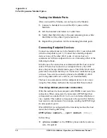
V

Verifying the cellular transceiver unit, 22

W

Warranty, 65

Содержание OM-AMPS-100

Страница 1: ...Communications Interface Cabinet Model No OM AMPS 100 including Model No OM MP8 100 8 Port Module Option and Model No OM BAT 100 Battery Option Installation Operation and Maintenance Manual 0049 0706...

Страница 2: ...nd does not represent a commitment on the part of Telenetics Corporation Telenetics Corporation assumes no responsibility for any inaccuracies that may be contained in this User s Guide Telenetics Cor...

Страница 3: ...nnecting the Endpoint Device 20 Powering Up OMEGA 21 Verifying the Cellular Transceiver Unit 22 Operating OMEGA 22 Activating Your Cellular Transceiver 22 Call Origination Testing 22 Call Answer Testi...

Страница 4: ...election Criteria 48 Antenna Placement 48 Distance from the Antenna to the Closest Cell Site 48 Degrees of Down tilt on the Cell Site Antenna Array 48 Obstacles between the Antenna and Cell Site 48 El...

Страница 5: ...nance Manual v Specifying a Default Port 60 Anti streaming 61 Command Summary 62 APPENDIX B WARRANTY COMPLIANCES 63 Warranty and RMA Statement 65 FCC Statement 67 FCC Interference Statement 67 FCC Par...

Страница 6: ...Table of Contents vi OMEGA Installation Operation and Maintenance Manual Notes...

Страница 7: ...the host computer can be provided by conventional land line or wireless cellular transceivers Product Overview OMEGA is a standalone single channel unit that provides a wireless cellular connection f...

Страница 8: ...resistant polycarbonate and is NEMA 4X certified The following list summarizes OMEGA s features c Telephone line interface emulation for an endpoint device equipped with an internal modem c Optional 8...

Страница 9: ...c enclosure Ancillary Documentation In addition to this manual the OMEGA documentation suite includes the following additional documents c OMEGA Communications Interface Cabinet Quick Start Guide Tele...

Страница 10: ...Preface 10 OMEGA Installation Operation and Maintenance Manual Notes...

Страница 11: ...stallation Operation and Maintenance Manual 11 Section 1 Installation Section 1 Contents Hardware Features 13 Finding a Suitable Location 14 Avoiding Hazards 15 Installing the OMEGA 15 Operating the O...

Страница 12: ...Section 1 Contents 12 OMEGA Installation Operation and Maintenance Manual...

Страница 13: ...Introduction This section describes how to install the OMEGA communications interface cabinet Hardware Features Figure 1 1 shows the hardware features of OMEGA The Battery and Battery Power Switch ar...

Страница 14: ...figuration application to evaluate the cellular telephone s receive signal strength see Section 4 Be sure there is sufficient space for OMEGA to connect to the endpoint device This distance should not...

Страница 15: ...me humidity While your OMEGA is ruggedized for extreme environments we recommend that the location you select does not expose OMEGA to harsh conditions c Locations prone to radio frequency or electro...

Страница 16: ...river and wrench c Flex type conduit if you are installing the unit outside c Optional a telephone handset In addition to the tools above the OMEGA cellular phone must be activated either by Telenetic...

Страница 17: ...he washer located between the nut and the antenna 2 Open the OMEGA enclosure and insert the antenna wire through the OMEGA antenna hole Then rest the antenna on the OMEGA antenna hole The bottom of th...

Страница 18: ...en making this connection use a UL listed and approved power cord with a rating of 10 amps or above The OMEGA enclosure is pre drilled with a hole that is 875 inches in diameter This hole is used to a...

Страница 19: ...erminal block on OMEGA by connecting the hot neutral and ground wires as follows The hot and neutral wires should be on the fused right side The ground wire should be on the left green yellow side NOT...

Страница 20: ...bove Connecting the Endpoint Device To connect an endpoint device to OMEGA 1 Insert the modem cable from the endpoint device through the conduit hole at the bottom of the compartment 2 If the OMEGA 8...

Страница 21: ...the battery terminal 3 Apply the 90 277 VAC power source to OMEGA 4 Close the AC fuse connector and move the Battery Power switch to the ON position see Figure 1 1 on page 13 5 Verify that the LEDs r...

Страница 22: ...tact Telenetics for more information Operating OMEGA After you set up OMEGA use the procedures in this section to test OMEGA s originate and answer capabilities WARNING Before you perform the followin...

Страница 23: ...OMEGA cellular transceiver can originate calls NOTE The modem that came with the endpoint device may provide additional ways to test the modem s dial out capabilities Refer to the manual that came wi...

Страница 24: ...Section 1 Contents 24 OMEGA Installation Operation and Maintenance Manual Notes...

Страница 25: ...EGA Operation and Maintenance Manual 25 Section 2 Troubleshooting Section 2 Contents Checking the Main Power Supply 27 Checking the Antenna 28 Checking the Battery Voltage 28 Reinitializing the OMEGA...

Страница 26: ...Section 2 Contents 26 OMEGA Installation Operation and Maintenance Manual...

Страница 27: ...OMEGA units equipped with the Battery option verify that the battery voltage is working properly see Checking the Battery Voltage on page 28 5 Verify that OMEGA can originate calls see Call Originatio...

Страница 28: ...3 2 Lift the AC fuse connector to remove AC power from OMEGA 3 Check the voltage between the red and black terminals at the battery see Figure 1 1 on page 13 The voltage should be approximately 12 5 t...

Страница 29: ...ications Section 3 Contents Operation 31 Modem Interface 31 Cellular Transceiver Interface 32 Battery Operation 32 Switches and LED Indicators 33 Power Supply 33 Mechanical Specifications 34 Connector...

Страница 30: ...Section 3 Specifications OMEGA Operation and Maintenance Manual 30...

Страница 31: ...device must meet PSTN and FCC 68 requirements and be compatible with all standard TELCO handshake signaling Modem Interface A standard RJ 11 modular jack connector provides the OMEGA s modem interface...

Страница 32: ...amp max transmit power 100 ma stand by RF output power 3 0 Watts maximum Antenna impedance 50 ohms Antenna type 50 ohm Omni directional VSWR is 1 2 0 or better over operating frequency Battery Operati...

Страница 33: ...e switching power supply is designed to operate from a wide range of AC input voltages and is isolated against voltage transients AC power input 90 to 277 VAC 50 to 60 Hz DC power input 100 to 150 VDC...

Страница 34: ...r antenna x 7 0 wide x 4 75 deep Mounting Centers 7 50 x 7 50 adjustable horizontal or vertical Weight 4 0 lbs Protection NEMA 4X watertight dust tight Flammability Rating UL94 5V Color Light gray Con...

Страница 35: ...Section 3 Specifications OMEGA Installation Operation and Maintenance Manual 35 Agency Compliance EMI RFI FCC 15 Class A computing devices UL UL 1950 Surge Protection IEC 801 4...

Страница 36: ...Section 3 Specifications 36 OMEGA Installation Operation and Maintenance Manual Notes...

Страница 37: ...Configuration Program Section 4 Contents Prerequisites 39 Getting Started 40 Reading the Cellular Telephone Signal 41 Programming a Telephone Number 42 Changing the Cellular Telephone s SID 43 Changi...

Страница 38: ...Section 4 Using the Configuration Program OMEGA Operation and Maintenance Manual 38...

Страница 39: ...r describes how to use the configuration software program to perform these tasks Prerequisites Before you use the OMEGA configuration software program you must c Have a PC equipped with a Microsoft Wi...

Страница 40: ...3 3 Connect the other end of the cable to your notebook computer s serial port 4 Apply 115 VAC power to OMEGA see Powering up OMEGA on page 21 The green Power LED goes ON 5 Exit to an MS DOS window c...

Страница 41: ...the Configuration Program on page 44 Reading the Cellular Telephone Signal The OMEGA configuration program uses a bar graph as a visual indication of the cellular telephone s receive signal strength U...

Страница 42: ...ompts you for a password see Figure 4 4 Figure 4 4 Password Prompt 2 Type the password and press Enter Initially there is no password so press Enter without typing any characters The message Checking...

Страница 43: ...4 6 New SID Prompt 3 Type the 5 digit SID You do not have to press Enter after typing The message Updating SID appears followed by SID updated Then the secondary menu reappears with the new SID displa...

Страница 44: ...MEGA configuration program To return to the default setting of no password repeat this procedure but press the Enter key in steps 3 and 4 without typing any characters NOTE If the password you type in...

Страница 45: ...ntenance Manual 45 Section 5 External Antenna Guidelines Section 5 Contents General Guidelines 47 External Antenna Selection Criteria 48 Types of External Antennas 50 Programming a Telephone Number 51...

Страница 46: ...Section 5 External Antenna Guidelines 46 OMEGA Installation Operation and Maintenance Manual...

Страница 47: ...e of an antenna can be increased by concentrating or focussing the signal Gain An antenna s gain is one of its identifying characteristics Terms such as unity gain 3dB gain and 9dB gain are common The...

Страница 48: ...ntact the local cellular carrier to obtain this information Degrees of Down tilt on the Cell Site Antenna Array Contact the local cellular carrier to find out this figure The greater the down tilt the...

Страница 49: ...nna to OMEGA Lay the connecting cable as straight as possible without kinks bends or twists If you need to keep the cable coiled use as large a radius for the coil as possible Keep in mind that althou...

Страница 50: ...ommend you use directional antennas designed to provide the maximum E R P allowed by FCC regulations and EIA standards Contact the cellular carrier in your area to determine the exact location of the...

Страница 51: ...of which type of external antenna you use reception and propagation patterns vary with the location To achieve the best results try different locations Even if a location appears adequate you should t...

Страница 52: ...Section 5 External Antenna Guidelines 52 OMEGA Installation Operation and Maintenance Manual Notes...

Страница 53: ...ual 53 Appendix A 8 Port Expansion Module Option Appendix A Contents Package Contents 55 Field Installation 55 Testing the Module Ports 58 Connecting Endpoint Devices 58 Specifying a Default Port 60 A...

Страница 54: ...Appendix A 8 Port Expansion Module Option 54 OMEGA Installation Operation and Maintenance Manual...

Страница 55: ...8 Port Expansion Module package contains the following items c One OMEGA 8 Port Expansion Module Model Number OM MP8 100 c Two plastic card guides c One short RJ 11 to RJ 11 cable c A diskette contai...

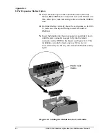
Страница 56: ...A unit 4 Hold the Module vertically above the card guides so its 8 RJ 11 jacks are at the top and facing toward the inside of OMEGA 5 Insert the Module into the card guide slots and slide it down unti...

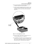
Страница 57: ...side of the Module Insert the other end into the OMEGA unit s RJ 11 jack on the unit s baseboard see Figure A 2 Figure A 2 Connecting the RJ 11 Jacks 8 Plug in all the RJ 11 cables from the external...

Страница 58: ...t When a host connects to an endpoint device the LED above the port being called remains green The LEDs for all other ports turn red to show that they are locked out until the host goes on hook You ca...

Страница 59: ...computer to OMEGA s DB 9 connector start a terminal emulation program such as HyperTerminal set up the program to use the parameters on page 62 and send the following command from the program PR 1 Ent...

Страница 60: ...ter In this command port number is a port number from 1 to 8 you want to specify as the default port Example Specifying OMEGA port 4 as the default port PD 4 Enter When OMEGA is configured with a defa...

Страница 61: ...a DTMF tone c OMEGA is powered up locally c The OMEGA Reset button is used to reset the unit c OMEGA is reconfigured Note If a port stays on hook after a bad train and remote disconnect the port is de...

Страница 62: ...owing parameters Data rate 9600 bps Data bits 8 Parity bit None Stop bit 1 Specify port number as the default port number Type PD port number and press Enter Disable default port operation Type PD 0 a...

Страница 63: ...OMEGA Operation and Maintenance Manual 63 Appendix B Warranty Compliances Appendix B Contents Warranty and RMA Statement 65 FCC Statement 67 Comments About This Manual 68...

Страница 64: ...Appendix B Warranty Compliances 64 OMEGA Installation Operation and Maintenance Manual...

Страница 65: ...arrangements will be at customer expense c Telenetics shall not be liable for any damage caused to the product in transit You acknowledge and agree that you will bear all risk of loss or damage to the...

Страница 66: ...nor and will consider this limited warranty voided if in Telenetics reasonable judgment there has been any 1 tampering with the Telenetics product s external label or serial number 2 attempt to open t...

Страница 67: ...protection against harmful interference in a residential installation This equipment generates uses and can radiate radio frequency energy and if not installed and used in accordance with the instruct...

Страница 68: ...etics invites all customers to communicate with us about any question or comment related to this manual Just fax phone or mail any question or comment to us Your suggestions help us improve the produc...

Страница 69: ...xternal antennas 50 Drilling conduit holes 16 Drilling mounting holes 16 E Eight port expansion module field installation 55 operation 58 overview 55 Elevated feed external antennas 50 Environmental s...

Страница 70: ...Power up 21 Prerequisites for OMEGA configuration program 39 Programming a telephone number 42 R Reading the cellular telephone signal 41 RMA 65 S Second dial tone method 59 Selecting an external ante...

Отзывы: