Section 1 Contents
OMEGA Installation, Operation, and Maintenance Manual
19
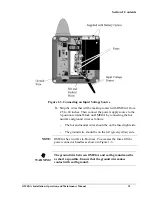
Figure 1-3. Connecting an Input Voltage Source
3.
Strip the wires that will be making contact with OMEGA from
.25 to .40 inches. Then connect the power supply source to the
3-position terminal block on OMEGA by connecting the hot,
neutral, and ground wires as follows:
-
The hot and neutral wires should be on the fused right side.
-
The ground wire should be on the left (green/yellow) side.
NOTE:
OMEGA has two 2A slo-blo fuses. To accesses the fuses, lift the
power connector handles as shown in Figure 1-3.
WARNING!
The ground wire between OMEGA and earth ground must be
as short as possible. Ensure that the ground wire makes
contact with earth ground.
Содержание OM-AMPS-100
Страница 6: ...Table of Contents vi OMEGA Installation Operation and Maintenance Manual Notes...
Страница 10: ...Preface 10 OMEGA Installation Operation and Maintenance Manual Notes...
Страница 12: ...Section 1 Contents 12 OMEGA Installation Operation and Maintenance Manual...
Страница 24: ...Section 1 Contents 24 OMEGA Installation Operation and Maintenance Manual Notes...
Страница 26: ...Section 2 Contents 26 OMEGA Installation Operation and Maintenance Manual...
Страница 30: ...Section 3 Specifications OMEGA Operation and Maintenance Manual 30...
Страница 36: ...Section 3 Specifications 36 OMEGA Installation Operation and Maintenance Manual Notes...
Страница 38: ...Section 4 Using the Configuration Program OMEGA Operation and Maintenance Manual 38...
Страница 46: ...Section 5 External Antenna Guidelines 46 OMEGA Installation Operation and Maintenance Manual...
Страница 52: ...Section 5 External Antenna Guidelines 52 OMEGA Installation Operation and Maintenance Manual Notes...
Страница 54: ...Appendix A 8 Port Expansion Module Option 54 OMEGA Installation Operation and Maintenance Manual...
Страница 64: ...Appendix B Warranty Compliances 64 OMEGA Installation Operation and Maintenance Manual...

