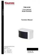
TBD-8100
© 2017
– Telefire Fire & Gas Detectors Ltd
Revision 1.00 November 2017
– Page 2 of 10 –
Table 1
Wiring Characteristics’ influence on System Performance
Use a two-wire cable
– it is recommended to use a twisted pair cable of 18 – 12 AWG.
Refer to the following table for maximum branch length per gives cable cross-section.
Use a shielded twisted-pair when connecting between buildings.
3.1.2 Cabling Planning
– control panel zone or input module IDC
Use a standard two-conductor cable with each conductor having a cross section of 0.8 to
3.3 mm
2
. Maximum loop resis
tance: 50Ω.
Table 2 specifies the maximum allowable length of cable, based on the cable’s cross
section
Cable Type
Cross Section
(mm
2
)
Detection Line Maximum Length for a
given Cross Section
AWG 18
0.8 mm
2
1,200 m
AWG 16
1.3 mm
2
1,900 m
AWG 14
2.1 mm
2
3,000 m
AWG 12
3.3 mm
2
4,800 m
Table 2
Maximum Length for an Input Line
3.1.3 Cabling Planning
– 24Vdc Supply
The module requires 24Vdc from the addressable control panel or an auxiliary power
supply such as the TPS-74A OR TPS-34A.
Use an auxiliary power supply whenever the module is installed a long distance from the
addressable control panel or whenever the total current consumption of all NACs
exceeds the capability of the addressable control panel's 24Vdc output.
3.1.4 Cabling planning
– shielded cables
It is recommended to avoid wiring outside buildings due to a risk of lightning strikes. If
required, it is mandatory to use shielded cables. The shielding must be grounded via the
control panel grounding terminals.
3.2
Installation
– Prior to Detector Positioning
3.2.1 Control Panel Detector Configuration
– Addressable Control
Panels
Configure the input addresses of the ADR-712, ADR-718, or ADR-812A as Input Circuit.
Please refer to the control panel’s technical instructions for further details concerning
device programming.
3.2.2 Input configuration in a control panel (TSA-1000 only)
Ensure that the input, to which the detector is connected, is configured at the panel as a
type D input (regular detectors zone). Please refer to the TSA-1000 technical manual for
a detailed explanation concerning the mode of configuring the various types of inputs.
3.3
Installation
– Placing the Detector
The TBD-8100 is designed to protect indoor fire risk areas, except environments where
smoke, steam, dust, or corrosive gasses are present under normal conditions.
Observe NFPA 72 guidelines and local fire codes when installing the detectors.


