background image


Initia

ting D

e

v

ic

e

s


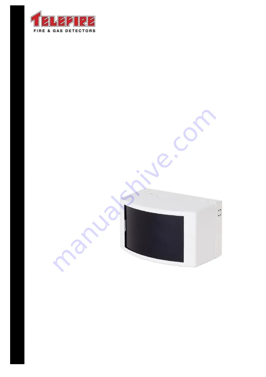
TBD-8100 

Conventional 

Beam Detector 


Technical Manual 


T

ELEFIRE 

F

IRE 

&


G

AS 

D

ETECTORS 

L

TD


PO Box 7036 
Petach Tikva 49250 
Israel 

Tel:    

972 3 970 0400 

Fax:   

972 3 921 1816 

eMail:  

[email protected] 

Web: 

www.telefire.co.il 

TBD-8100En100.pdf 

Revision 1.00 

November 2017 


Содержание TBD-8100

Страница 1: ...nal Beam Detector Technical Manual TELEFIRE FIRE GAS DETECTORS LTD PO Box 7036 Petach Tikva 49250 Israel Tel 972 3 970 0400 Fax 972 3 921 1816 eMail info telefire co il Web www telefire co il TBD 8100...

Страница 2: ...72 guideline and UL standards and Fault as used in EN 54 standards are used interchangeably throughout this manual i Note Do not install operate and maintain this product before fully reading this man...

Страница 3: ...7000 GUARD 7 and ADR 3000 Analog Addressable Control Panel when used with an ADR 712 ADR 718 or ADR 812A Input module 3 Installation Planning of quantity and location of detectors shall be done accor...

Страница 4: ...om the addressable control panel or whenever the total current consumption of all NACs exceeds the capability of the addressable control panel s 24Vdc output 3 1 4 Cabling planning shielded cables It...

Страница 5: ...e detection coverage on each side of the beam is 9 meters maximum Place the detector up to 9 meters from the wall or 18 meters from the next similar parallel detector under a flat ceiling i Note Insta...

Страница 6: ...o the zone input in the control panel or to the addressable input assembly use a model TRA 1B adapter see Figure 3 Figure 3 Connecting to the zone input in a control panel or to an addressable assembl...

Страница 7: ...the detector s signal strength amplification and type of fault the letter F appears in one of the screen s locations a More than 50 dust accumulation on the detector b More than 90 dust accumulation o...

Страница 8: ...ects to the detector via two conductors Connect the optional indicator module to the detector as described in the drawing Figure 6 Connection of an Optional TBD 8100R Indicator Assembly to the Detecto...

Страница 9: ...ltage supplied to the detector 4 If the number of lit LEDs starts decreasing you are moving away from the optimum direction Retract until you reach a maximum number of lit LEDs 5 Measure the voltage b...

Страница 10: ...less than 10 m there is a need to attach the black patch supplied with the detector onto the transmitter s lenses The detector would signal by lighting up the red led during the initial adjustment tha...

Страница 11: ...70 of the prism and induce an alarm This action can also be carried out by bringing a magnet near the display LED in the optional TBD 8100R module provided the LED is connected to the detector 7 Ensur...

Страница 12: ...e or Alarm State 20mA during calibration 50mA Local Indication normal status HL4 LED flashes for 0 3 seconds once every 4 seconds Alarm HL4 LED constantly lit Fault The HL4 LED flashes every second Er...

Отзывы: