background image

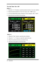
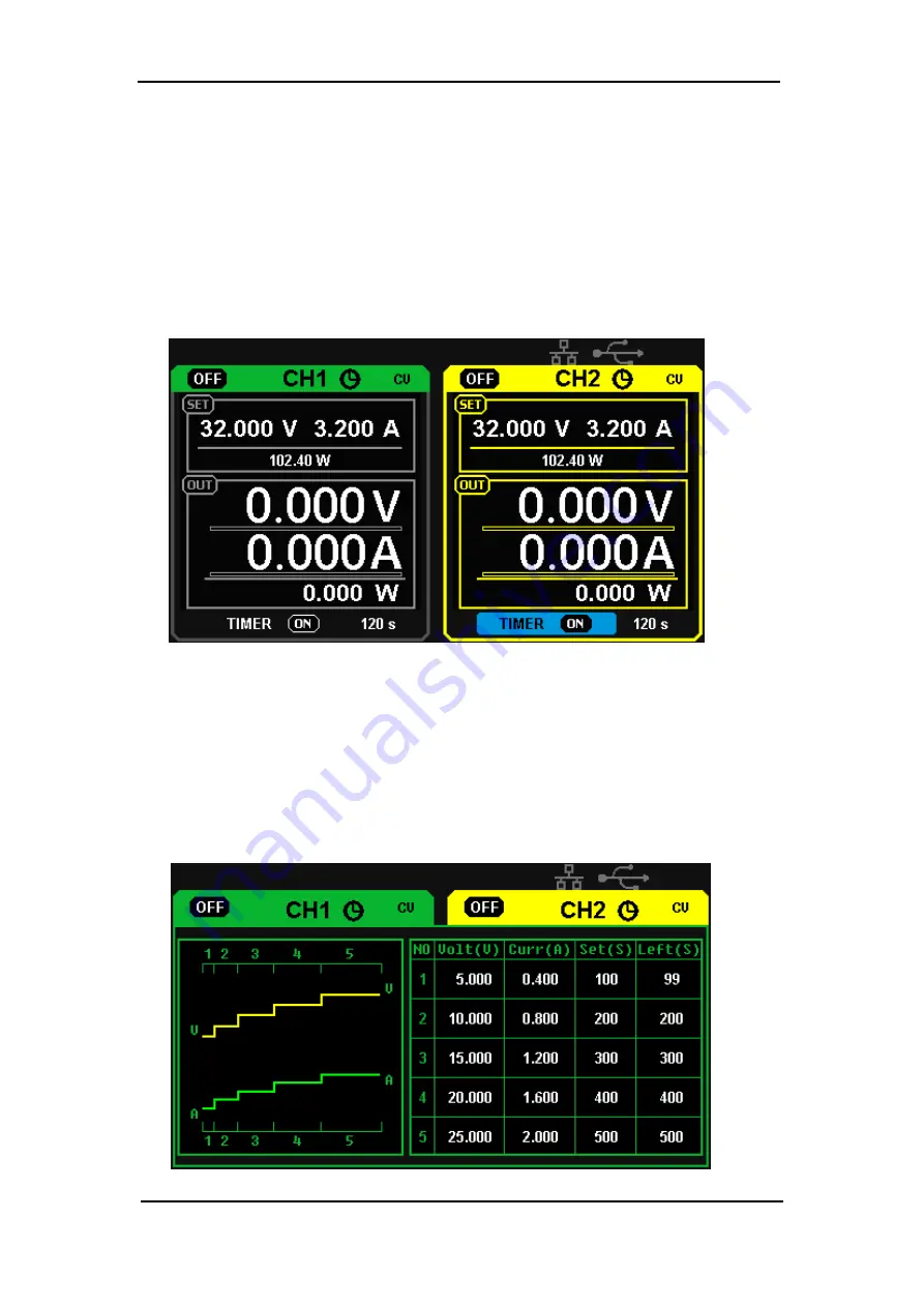
Turn the Timer On or Off

Method 1:

1.  Press the “1” or ”2” button to select the desired channel on the main interface.

2.  Press the direction button to move the cursor to the “TIMER” menu.

3.  Turn the multi-function knob to change the Timer setting to “ON” or "OFF".

4.  Press the knob to enter the Timer setting.

Method 2:

1.  Press the “Timer” button to enter the timer interface.

2. Press the “1” or ”2” button to select the desired channel.

3.  Press the multi-function knob to start the Timer.

4.  Press the knob again to turn off the Timer

20  Quick Start

Содержание T3PS3000

Страница 1: ...T3PS3000 Programmable DC Power Supply Quick Start Guide Version 1 3 September 2018 ...

Страница 2: ...d Teledyne Test Tools is a brand and trademark of Teledyne LeCroy Inc Other product or brand names are trademarks or requested trademarks of their respective holders Specifications prices availability and delivery subject to change without notice ...

Страница 3: ...ut Check 9 Chapter 2 Control Panel Operation 10 2 1OutputSummary 11 2 2 CH1 CH2 Independent Output 13 2 3 CH3 Independent Mode 14 2 4 CH1 CH2 Series Mode 15 2 5 CH1 CH2 Parallel Mode 16 2 6 LAN Setting 17 2 7 Save and Recall 18 2 8Timer 19 2 9 Waveform Display 22 2 10 Version Information 23 Chapter 3 Remote Control 24 3 1 Syntax Conventions 25 3 2 Command List 26 3 3 Command Description 27 Chapter...

Страница 4: ...ument read the manual to understand the input output ratings Do not operate with suspected failures If you suspect that the instrument is damaged contact the Teledyne LeCroy service department immediately Do not operate in wet damp conditions Do not operate in an explosive atmosphere Keep the surface of the instrument clean and dry Avoid touching exposed circuits or wires Do not touch exposed cont...

Страница 5: ...me or Chassis Terminal ON Standby Power Alternating Current Operating Environment Temperature 0 C to 40 C Humidity 5 to 90 relative humidity non condensing up to 30 C Upper limit derates to 50 relative humidity non condensing at 40 C Altitude 2000 m AC Power AC Input Voltage and Frequency 100V 120V 220V 230V 10 at 50 60Hz Manual AC Selection with two slide switches Power Consumption 380 Watts 490 ...

Страница 6: ...ion Main features 4 3 TFT color LCD display Three independent outputs two of which are adjustable with a total power of up to 195W Four power line input voltage values of 100V 120V 220V and 230V 10 50 60Hz Store and call setting parameters Timing output function Waveform display Real time display of voltage or current waveforms and digital display of voltage current and power values Automatic scre...

Страница 7: ... display Interface of the power supply as well as the unpacking and first use inspection Reading this chapter will give you a quick understanding of the basic power supply operation Brief introduction General Inspection The front panel The rear panel User interface The rear panel Output check ...

Страница 8: ...he power supply to Teledyne LeCroy for service or calibration The consigner or carrier will be responsible for damage to the instrument resulting from shipping Teledyne LeCroy will not provide free maintenance or replacement in this instance 2 Inspect the instrument If the instrument is found to be damaged defective or fails in electrical or mechanical tests please contact the Teledyne LeCroy serv...

Страница 9: ...Please use the power cord provided and adjust the DIP Switches to the local AC line voltage then connect the instrument to AC power 1 Set the DIP Switches to the local AC power voltage 2 Connect the power cord to the T3PS3000 before connecting the power cord to wall socket 3 Use a DMM to check the power cord ground pin is connected to the T3PS3000 ground terminal then attach the power cord to the ...

Страница 10: ...witch 2 Carrying Handle 9 Power Switch 3 System parameter configuration buttons 10 CH1 Output Terminals 4 Multi function knob 11 Ground Terminal 5 Fine Adjust button 12 CH2 Output Terminals 6 Right Left Direction buttons 13 CH1 and CH2 CV CC indicator lights 7 Channel Control buttons 14 CH3 Output Terminal 15 CH3 Run Overload Indicator ...

Страница 11: ...rage function Interface Press the timer button to enter timer settings interface Hold the button pressed to turn on off the keylock function A short press of the button will turn on the system information interface Buttons for controlling the channel Press the All On Off button to turn all the channels on or off Press the 1 button to select CH1 as the current channel Press the 2 button to select C...

Страница 12: ...n Press the button to move the cursor The output terminals on the front panel The output terminals of CH1 CH2 and CH3 are clearly labelled and include a positive terminal in red a negative terminal in black and a common ground in green for CH1 and CH2 The operation details are introduced in the following control panel operation section ...

Страница 13: ...erating mode logo The corresponding letters will be displayed depending on which mode the channel is in either CV or CC mode 4 LAN logo It will display when there is a LAN connection 5 USB logo It will display when there is a USB connection 6 Voltage value 7 Current value 8 Power value 9 Timer lD Timer state identification 10 Channel on off logo 1 2 3 3 4 5 7 6 8 9 10 ...

Страница 14: ... for the AC input voltage This should be set before use 3 The description of the AC input voltage and fuse ratings 4 AC power socket 5 The fan air vents 6 CE certification mark 7 USB interface and identification 8 LAN interface and identification 9 TÜV certification mark 1 2 3 6 4 5 7 8 9 ...

Страница 15: ...tputs and check that the instrument is working in constant voltage mode CV on the display of each channel Check whether the output voltage value can be adjusted from 0V to 32V Current Output Check 1 Turn on the power and make sure the current setting values of all channels are not zero 2 Use an insulated wire to connect the positive and negative terminal of CH1 CH2 3 Turn on CH1 CH2 and check that...

Страница 16: ...unction and operation of the power supply control panel will be covered in detail Output summary CH1 CH2 independent output CH3 independent output Series output Parallel output LAN setting Save and recall Timer Waveform display Version information Firmware upgrade Keylock ...

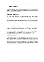
Страница 17: ...de independent or tracking mode the current value is set and controlled through the front panel The output current will follow the front panel user set output current level provided that the output voltage value is less than it s maximum preset voltage value If less current is required by the target system then the output will switch to constant voltage mode only returning to constant current mode...

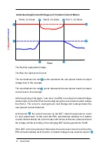
Страница 18: ...along the user present output voltage line Part A The current is varying due to load change but is always below the user present current threshold At time point the current has risen by the DUT current requirement to reach it s user preset level At this point the PSU automatically switches to Constant Current mode whereby the current output will remain at the user preset level and the voltage will...

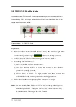
Страница 19: ...d to the positive and negative terminals of CH1 or CH2 3 Set voltage and current value of CH1or CH2 a Press 1 2 button to select the wanted channel b Move the cursor through direction button to select the wanted parameter voltage current c Press Fine to select the digit position and then adjust the multi function knob to change the corresponding parameter 4 Turn on the output Press the on off butt...

Страница 20: ...o 3 2A Operation 1 Connect the load to the positive and negative terminals of CH3 on the front panel 2 Select the wanted voltage value by moving the CH3 DIP switch 3 Turn on the output Press on off button to turn on the output the corresponding indicator light is lit immediately When the current value is higher than 3 2A the overload indicator light turns red and the working mode turns to CC mode ...

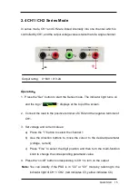
Страница 21: ...positive terminal of CH2 and the negative terminal of CH1 3 Set voltage and current values a Press the 1 button to select the channel 1 b Use the direction buttons to move the cursor to the desired parameter voltage current c Press Fine to select the digit position and then turn the multi function knob to change the corresponding parameter value 4 Press the on off button corresponding to CH1 to tu...

Страница 22: ...load to the positive and negative terminal of CH1 3 Set voltage and current value a Press 1 button to select the channel 1 b Use the direction button to move the cursor to the desired parameter voltage current c Press Fine to select the digit position and then revolve the multi function knob to change the corresponding parameter 4 Press on off button corresponding CH1 to turn on the output Note Yo...

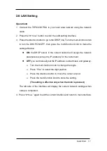
Страница 23: ...ill assign the network parameters such as the IP address for the instrument OFF you can manually set the IP address subnet mask and gateway Turn the multi function knob to change the digits Press Fine to select the digit position Press the direction button to move the cursor around Press the multi function knob to store the setting The setting is effective only when the knob is pressed The left si...

Страница 24: ...the cursor to OPER CHOICE 6 Move the cursor to STORE by turning the multi function knob then press it to save the current setup Recall Setup 1 Short press the IP Store button then long press the IP Store button to enter Store Recall interface 2 Press the direction button to move the cursor to FILE CHOICE 3 Select the desired file by turning the multi function knob 4 Press the direction button to m...

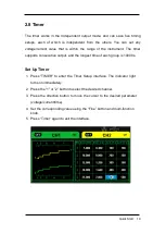
Страница 25: ...tive output and the longest time of each group is 10000s Set Up Timer 1 Press TIMER to enter the Timer Setup interface The indicator light turns on immediately 2 Press the 1 or 2 button to select the desired channel 3 Press the direction button to move the cursor to the desired parameter voltage current time 4 Set the corresponding value using the Fine button and multi function knob 5 Press Timer ...

Страница 26: ...o the TIMER menu 3 Turn the multi function knob to change the Timer setting to ON or OFF 4 Press the knob to enter the Timer setting Method 2 1 Press the Timer button to enter the timer interface 2 Press the 1 or 2 button to select the desired channel 3 Press the multi function knob to start the Timer 4 Press the knob again to turn off the Timer 20 Quick Start ...

Страница 27: ... is running the countdown will stop The countdown will resume when the channel output is turned on again The Timer will automatically turn off when the time reduces to 0 Note The timer function is invalid when the series mode or parallel mode is turned on Quick Start 21 ...

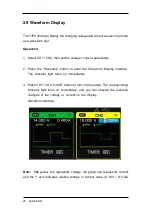
Страница 28: ...orm Display interface The indicator light turns on immediately 3 Press CH1 CH2 On Off button to turn on the output The corresponding indicator light turns on immediately and you can observe the real time changes of the voltage or current on the display Waveform interface Note The yellow line represents voltage the green line represents current and the Y axis indicates relative voltage or current v...

Страница 29: ...he button to lock the interface which will lock all the buttons and knobs The lock icon will be displayed Long press again to turn off the keylock function The lock icon will no longer be illuminated and the knobs and buttons will become functional again Quick Start 23 Short press of the ...

Страница 30: ... on the rear panel SCPI Standard Commands for Programmable Instruments is an ASCII based programming language that can be used to control the power supply from a remote computer installed with NI Measurement Automation software In this chapter we introduce the SCPI commands supported by the T3PS3000 Quick Start 24 ...

Страница 31: ...al bar separates parameter choices For example CH1 CH2 in the above command indicates that you can specify a channel The bar is not sent with the command string Angle brackets indicate that you must specify a value for the enclosed parameter For example the above syntax statement shows the voltage parameter in angle brackets You must specify a value for the parameter for example CH1 VOLT 10 The an...

Страница 32: ...4 INSTrument Subsystem 5 MEASure Subsystem 6 CURRent Subsystem 7 VOLTage Subsystem 8 OUTPut Subsystem 9 TIMEr Subsystem 10 SYSTem Subsystem 11 IPaddr Subsystem 12 MASKaddr Subsystem 13 GATEaddr Subsystem 14 DHCP Subsystem Quick Start 26 ...

Страница 33: ...cal Return T3 Teledyne Test Tools T3PS3000 PS00001130025 1 01 01 01 02 V3 0 2 SAV Command format SAV 1 2 3 4 5 Description Save current state in nonvolatile memory Example SAV 1 3 RCL Command format RCL 1 2 3 4 5 Description Recall state that had been saved from nonvolatile memory Example RCL 1 4 INSTrument Command format INSTrument CH1 CH2 Description Select the channel that will be operated Exam...

Страница 34: ...hannel Example MEASure CURRent CH1 Typical Return 3 000 Command format MEASure VOLTage CH1 CH2 Description Query voltage value for specified channel if there is no specified channel query the current channel Example MEASure VOLTage CH1 Typical Return 30 000 Command format MEASure POWEr CH1 CH2 Description Query power value for specified channel if there is no specified channel query the current ch...

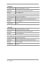
Страница 35: ...tion Query the current value of the selected channel Example CH1 CURRent Typical Return 0 500 7 VOLTage Command format CH1 CH2 VOLTage voltage Description Set voltage value of the selected channel Example CH1 VOLTage 25 Command format CH1 CH2 VOLTage Description Query the voltage value of the selected channel Example CH1 VOLTage Typical Return 25 000 29 Quick Start ...

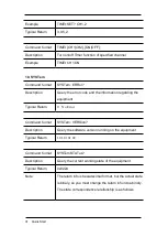
Страница 36: ...format OUTPut WAVE CH1 CH2 ON OFF Description Turn on off the Waveform Display function of specified channel Example OUTPut WAVE CH1 ON 9 TIMEr Command format TIMEr SET CH1 CH2 1 2 3 4 5 voltage current time Description Set timing parameters of specified channel including group 1 2 3 4 5 voltage current time Example TIMEr SET CH1 2 3 0 5 2 Command format TIMEr SET CH1 CH2 1 2 3 4 5 Description Que...

Страница 37: ... the equipment Typical Return 0 No Error Command format SYSTem VERSion Description Query the software version running on the equipment Typical Return 1 01 01 01 02 Command format SYSTem STATus Description Query the current working state of the equipment Typical Return 0x0224 Note The return info is hexadecimal format but the actual state is binary so you must change the return info into a binary T...

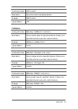
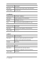
Страница 38: ...aveform diplay 11 IPaddr Command format IPaddr IP address Description Assign a static Internet Protocol IP address for the instrument Example IPaddr 10 11 13 214 Note The command is invalid when DHCP is used Command format IPaddr Description Query the current IP address of the instrument Typical Return 10 11 13 214 12 MASKaddr Command format MASKaddr NetMasK Description Assign a subnet mask for th...

Страница 39: ...command is invalid when DHCP is used Command format GATEaddr Description Query the current gateway of the instrument Typical Return 10 11 13 1 14 DHCP Command format DHCP ON OFF Description Assign the network parameters such as the IP address for the instrument automatically Example DHCP ON Command format DHCP Description Query whether the automatic network parameters configuration function is tur...

Страница 40: ...ou may continue to use the power supply but we suggest that you decrease the output load Question 3 Is it normal that in series mode the voltage and current values of one channel may be 0 while those of another channel are not 0 Answer 3 Yes because when current output load is higher than the limited current value the working mode turns to CC from CV Question 4 On startup why is the observed value...

Страница 41: ......
Страница 42: ...ve focused on creating products that improve productivity by helping engineers resolve design issues faster and more effectively Oscilloscopes are tools used by designers and engineers to measure and analyze complex electronic signals in order to develop high performance systems and to validate electronic designs in order to improve time to market The Teledyne Test Tools brand expands on the Teled...

Отзывы: