Time
V
o
lt
a
g
e
a
n
d
C
u
rr
e
n
t
Part A, CV Mode
Part B, CC Mode
Part C, CV Mode
1
2
3
4
1
2
1
2
4
3
4
3
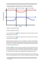
The Red line represents Voltage.
The Blue line represents Current.
The level between the two
points represents the user preset maximum output
voltage level in this example.
The level between the two
points represents the user preset maximum output
current level in this example.
At the beginning of the graph, “zero time”, the PSU is running in Constant Voltage
mode shown by the thick Red line tracking along the user present output voltage
line, Part A. The current is varying (due to load change) but is always below the
user present current threshold.
At time point
the current has risen by the DUT current requirement, to reach
it’s user preset level. At this point the PSU automatically switches to Constant
Current mode whereby the current output will remain at the user preset level and
the voltage will fall according to the changing DUT load requirements, Part B.
If the DUT current requirement falls below the user preset current level then the
PSU will automatically switch back to Constant Voltage mode as show at point
12 Quick Start
Understanding Constant Voltage and Constant Current Modes
Содержание T3PS3000
Страница 1: ...T3PS3000 Programmable DC Power Supply Quick Start Guide Version 1 3 September 2018 ...
Страница 41: ......


