ААНЗ.464414.001-03.61 РЭ p.21
Figure 2
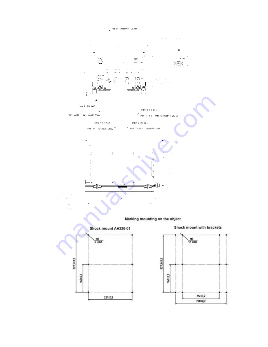
– Power Amplifier Assembly Drawing
Страница 1: ...HF Radio R 1150 00 Operation Manual 464414 001 61 Type...
Страница 2: ...1150 02 version 33 1 1 4 Setting and Performance 37 1 1 4 1 Radio operation in the transmit mode 37 1 1 4 2 Radio operation in the receive mode 38 1 1 4 3 Radio operation during the Antenna Coupler s...
Страница 3: ...nd Maintenance Manual is intended for qualified specialists who have special training in operation of the radio of the given type and on the air operation and skills in PC operation ATTENTION Serious...
Страница 4: ...the 20 39 304 76 National Standard The R 1150 01 R 1150 02 radios meet the requirements specified for the equipment of the 1 7 1 8 groups with the exception of lowered operating temperature according...
Страница 5: ...ation in compliance with Data Link Layer Protocol ARQ which provides automatic request for repeat or retransmission Electronic Protection Measures EPM protect communications from hostile interference...
Страница 6: ...specifications Parameter Value 1 2 Frequency range kHz 1500 to 29999 99 Channel Spacing Hz 10 Frequency Stability 3 10 7 Emission Modes receiving A1A J3E B8E 3E 3 F1B in modem FSK mode Emission Modes...
Страница 7: ...iver output tone frequency 1 Hz 1000 100 Receiver PEP output 1 J3E at 50 ohm W for 150W R 1150 00 radio 100 capacity 107 to 214 50 capacity 53 5 to 107 25 capacity 27 to 53 5 12 5 capacity 13 5 to 27...
Страница 8: ...5 Net presets not less 400 Harmonic suppression dB not more for 150W R 1150 00 radio minus 50 for 400W R 1150 01 radio minus 60 for 1000W R 1150 02 radio minus 60 Transmitter non linear distortion le...
Страница 9: ...is equipped with the input to be connected to the local area network LAN Such connection provides data transmission and control of the radio from the remote PC Remote control and data transmission are...
Страница 10: ...ta modem settings Standard notation Modulation coding Data rate bps MIL STD 188 110B APPENDIX F E PSK QAM 9600 12800 16000 19200 STANAG4539 MIL STD 188 110B E PSK QAM 3200 4800 6400 8000 9600 N 12800...
Страница 11: ...tweight Headset 468624 001 1 Lightweight Handset HHS 250MICAM 1 Loudspeaker 420 with 467291 004 61 1 AH420 UX1 cable 685692 335 1 AH210 01 Antenna Coupler 468567 026 1 220 01 Power Amplifier 468733 01...
Страница 12: ...e 685691 203 61 1 R 1150 03 UX1 cable 685623 050 61 1 C signal cable 685669 001 61 1 6 6g 16 58 019 7805 70 bolt 16 5 6g 20 21 12 18 10 GOST 11738 84 screw 2 6 6g 16 88 019 GOST 11738 84 screw 8 6 6g...
Страница 13: ...for HF radio R 1150 01 Product component name Designation design document Amount items Note 1 2 3 4 Radio transmitting device consisting of 464424 040 1 Transceiver 300 464511 011 61 1 Control unit W...
Страница 14: ...685623 043 1 cable R 1150 UX8 685623 044 03 1 cable R 1150 UX3 685661 097 1 cable R 1150 UX9 685661 152 1 cable R 1150 UX6 685661 153 03 1 cable R 1150 UX14 685631 011 1 FGN 0F 305 CLC LEMO 1 FGN 2F 3...
Страница 15: ...68339 002 01 61 1 Lightweight Headset 468624 001 1 Handset HHS 250MICAM 1 Antenna coupler 210 10 468567 026 1 Loudspeaker A 420 467291 004 61 1 Dipole antenna KUA 35 6 1000 1 Antenna AD 4 1 Assembly p...
Страница 16: ...e major components of the R 1150 radio are the following 300 Transceiver Unit WV355 Control Unit 220 01 Power Amplifier 210 01 Antenna Coupler DC Power Supply Unit The major components of the 1150 01...
Страница 17: ...3 044 61 R 1150 UX8 5 3 0 9 685661 097 61 R 1150 UX3 10 15 20 25 30 35 40 50 60 75 685661 152 61 R 1150 UX9 1 62 685661 153 61 R 1150 UX6 5 3 0 35 685691 200 61 R 1150 UX10 3 0 6 685691 203 61 R 1150...
Страница 18: ...5661 153 61 R 1150 UX6 1 1 685691 203 61 R 1150 UX12 0 6 685691 203 61 R 1150 UX13 3 5 1 1 3 1 1 Installation of the radio major components 1 1 3 1 2 Installation of the 300 Transceiver The Transceive...
Страница 19: ...464414 001 03 61 p 19 Figure 1 300 Transceiver Unit Assembly Drawing...
Страница 20: ...r AH220 01 The Power Amplifier is installed into the mobile objects using the AH220 01 shock mount PA brackets and fasteners The order of installation Install the Power Amplifier onto the shock absorb...
Страница 21: ...464414 001 03 61 p 21 Figure 2 Power Amplifier Assembly Drawing...
Страница 22: ...kets while installing the Power Amplifier into the mobile objects 1 1 3 1 4 Installation of the Antenna Coupler 1 1 3 1 5 The Antenna Coupler is installed into the mobile objects using fasteners The A...
Страница 23: ...464414 001 03 61 p 23 Figure 3 AH210 01 Antenna Coupler Assembly Drawing 1 1 3 1 6 Installation of the AH570 DC DC Power Supply Unit...
Страница 24: ...y Unit assembly drawing is presented in Figure 2 Note There is no need to use brackets while installing the DC Power Supply Unit into the mobile objects 1 1 3 1 7 Installation of the Fill Gun Programm...
Страница 25: ...mission The headset allows the operator to perform other activities during the reception and transmission of spoken information e g to make records while receiving the information The headset is secur...
Страница 26: ...464414 001 03 61 p 26 Figure 5 Headset Assembly Drawing Figure 6 View of the headset placement on the operator s head...
Страница 27: ...fier are installed into the mobile objects using the mounting rack and fasteners Order of installation install the cushions from the packaging set onto the mounting rack with mounted power amplifier a...
Страница 28: ...464414 001 03 61 p 28 Figure 8 AH300 Transceiver WV355 Control Unit and AH220 04 Power Amplifier Assembly Drawing...
Страница 29: ...ation is shown in Figure 9 Figure 9 The layout of fastening of the radio s mounting rack onto the object of installation 1 1 3 2 2 Installation of the Antenna Coupler The Antenna Coupler is installed...
Страница 30: ...1 3 2 3 Installation of the Fill Gun Programmer Device Fill gun Install the fill gun as described in par 1 1 3 1 7 1 1 3 2 4 Headset installation Install the headset as described in par 1 1 3 1 8 1 1...
Страница 31: ...l the cushions from the packaging set onto the mounting rack with mounted power amplifier and power supply unit and secure with bolts install the transceiver with control unit to the wedge bars of the...
Страница 32: ...464414 001 03 61 p 32 Figure 11 Installation and connection of the transceiver AH300 control unit WV355 power amplifier AH220 10 and power supply AH500 10...
Страница 33: ...tion is shown in Figure 12 Figure 12 The layout of fastening of the radio s mounting rack onto the object of installation 1 1 3 3 2 Installation of the Antenna Coupler The Antenna Coupler is installed...
Страница 34: ...r Assembly Drawing 1 1 3 3 3 Installation of the Fill Gun Programmer Device Fill gun Install the fill gun as described in par 1 1 3 1 7 1 1 3 3 4 Headset installation Install the headset as described...
Страница 35: ...es in listening modes operation on fixed frequencies in listening modes and data transmission modes operation in the ALE mode operation in FHSS mode 1 1 4 1 Radio operation in the transmit mode During...
Страница 36: ...the bypass is switched on in the Power Amplifier and the signal is sent from the unit s input to the output with the minimum loss and then to the Transceiver Unit input In the Transceiver Unit the sig...
Страница 37: ...eset frequency has not been set during the fixed frequencies operation setting will be done automatically during the first radio transmission session This frequency will be stored into the radio s mem...
Страница 38: ...nce is not provided Table 7 Radio capability when the DM mode of operation is selected Transmitted information built in modem standard Emission class J3E USB J3E LSB B8E H3E A1A A3E F1B Analog telepho...
Страница 39: ...External modems MIL STD 188 110B APPENDIX F STANAG4539 MIL STD 188 110B MIL STD 188 110A 5 3 Programmable FSK STANAG 4444 Note In the table is denoted performance is provided performance is not provi...
Страница 40: ...e set of parameters that define the radio configuration to be used in the specific network i e network name mode of operation FHSS key preset parameters of the channel preset parameters of the modem b...
Страница 41: ...meters set can be changed at any time during the radio performance The radio is capable to change parameters manually and allows to set their new values that are valid right after their entering and a...
Страница 42: ...bit rates 2400 and 1200 bps Digital telephony mode can be used only in radios of the R 1150 00 type and cannot be used to operate with analog radios 1 1 4 11 ALE mode The radio provides operation in...
Страница 43: ...ethod with the specific radio set If the calling station cannot establish the link on the best channel it tries to make a call on a subsequent channel In case when the analysis is of the same values f...
Страница 44: ...state that it is shared with the other stations in the networks the radio operates in ALE controller that implements the function of automatic link establishment selects the link with optimal quality...
Страница 45: ...cteristics of the received signal and then exchange with received information The difference between this method and the sounding method is that both calling and responding stations exchange the infor...
Страница 46: ...rformance it is possible to exclude some frequencies from the hopping band i e the radio will use not all frequencies between assigned limits of hopping While operating in the frequency hopping mode t...
Страница 47: ...used by all radios to synchronize their clocks The requesting station while sending the request for synchronization to the main station is trying to receive special synchronizing transmission While op...
Страница 48: ...ide the remote control from the PC the PC where the 00150 01 61 34 01 Operator s Manual radio control program is installed should be connected to the CONTROL connector of the Transceiver Unit The radi...
Страница 49: ...uipment The radio can be interconnected with the data modems with analog output and the analog encoding equipment Data transmission from the external modems and analog encoding equipment is made over...
Страница 50: ...requency generator The radio can be interconnected with the high stable standard frequency generator The nominal frequency of the external generator should be 10 MHz The radio provides normal intercon...