TMG7800 Series System Installation Guide
32
4.3.2.2
1+1 Configuration
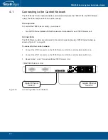
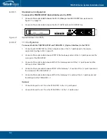
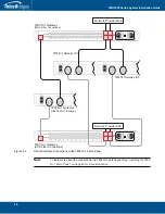
To connect both the 7800-DS3 and 7800-DS3+1 to the PSTN:
1.
Connect each DS3 line from the network section of the 1+1 patch panel to the remote equipment.
See
figure
4.6 on page
32.
2.
Connect each DS3 line from the DS3 connectors labeled
Gateway
of the 1+1 patch panel to the
7800-DS3.
3.
Connect each DS3 line from the DS3 connectors labeled
1+1
of the 1+1 patch panel to the 7800-
DS3+1.
Optional
1.
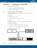
Connect bits port 0 and 1 from the 7800-DS3 to the 1+1 patch panel
2.
Connect bits port 0 and 1 from the 7800-DS3+1 to the 1+1 patch panel
Figure
4.6
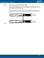
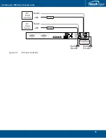
7800-DS3 and 7800-DS3+1 connecting to the TDM 1+1 DS3 1+1 patch panel
Gateway
Gateway 1+1 Network
Gateway 1+1 Network
Gateway 1+1 Network
1+1
Network
2
MGMT0
ETH
VOIP
0
1
0
1
TMS
0
1
MGMT0
ETH
VOIP
0
1
0
1
TMS
0
1
7800-DS3+1
7800-DS3
(sample DS3 ports 0 connection shown)
Connect to network
Содержание 7800 N+1
Страница 1: ...Installation Guide 7800 Series Gateway November 3 2017...
Страница 8: ...TMG7800 Series System Installation Guide viii...
Страница 30: ...TMG7800 Series System Installation Guide 22...
Страница 52: ...TMG7800 Series System Installation Guide 44...
Страница 75: ...67 Appendix A Wiring Diagrams...

