TMG7800 Series System Installation Guide
56
7.2.4
7800 N+1 Patch Panel
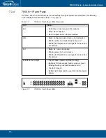
Once the 7800 N+1 Patch Panel has run successfully through its system boot procedures, the following
will be displayed as described in
table
7.3 on page
56:
Table
7.3
7800 N+1 Patch Panel LEDs Description
Figure
7.2
7800 N+1 Patch Panel LEDs
LED
Display
Net
• Solid Green: Laser received from network.
• Black: Not configured.
• Red: Configured but no laser is received.
GW
• Black: Configured normal state, or not configured.
• Blinking yellow: Unit replaced by backup unit.
• Blinking red: Replaced but no signal is received from
the network.
N+1
• Black: N+1 unit is in standby.
• Blinking green: N+1 unit is active.
• Blinking red: Replaced but no signal is received from
the network.
4 LEDS to the far right
• Top left: Green (power on); Red (booting)
• Bottom left: Green steady (ready); yellow or green
blinking (booting); red (boot sequence error)
• Top right: Unused
• Bottom right: Black (patch panel OK); red (hardware
failure)
1
3
5
7
9
11
13
0
2
4
6
8
10
12
14
NET
G
W
N+1
0
ETH
1
Содержание 7800 N+1
Страница 1: ...Installation Guide 7800 Series Gateway November 3 2017...
Страница 8: ...TMG7800 Series System Installation Guide viii...
Страница 30: ...TMG7800 Series System Installation Guide 22...
Страница 52: ...TMG7800 Series System Installation Guide 44...
Страница 75: ...67 Appendix A Wiring Diagrams...


