background image

GW-482S INSTALL ATION GUID E 


21


MN100143 Rev B


9. 

T ake the supplied RJ45 cables from the plastic bag. 

10. 

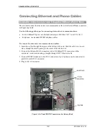
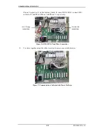
Connect one end of an RJ45 cable to the Ethernet Port2 on the Gateway board. Connect 
the  other end to  the L2 port  on the Patch Panel. 


Figure 24: LAN Port 2 Connections 

11. 

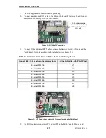
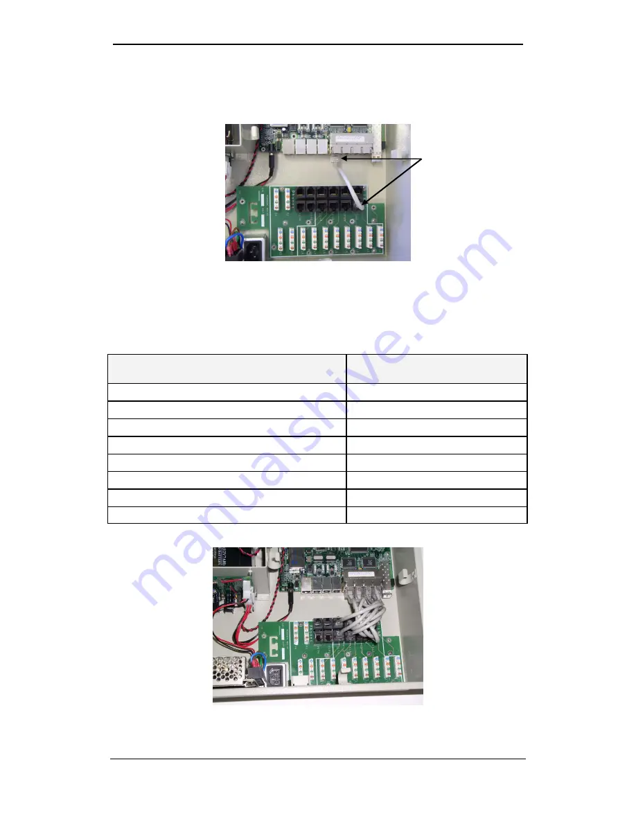
Connect all the additional RJ45 cables between the Gateway Board LAN ports and the 
Patch Panel LAN ports as shown in the table below (see Figure 25). 

Table 4: LAN Connections between Patch Panel and Gateway Board 

Connect RJ45 Cables between the Gateway Board-    and the LAN ports on the Patch Panel: 

Ethernet Port 1  to 

L1 

Ethernet Port 2  to 

L2 

Ethernet Port 3  to 

L3 

Ethernet Port 4  to 

L4 

Ethernet Port 5  to 

L5 

Ethernet Port 6  to 

L6 

Ethernet Port 7  to 

L7 

Ethernet Port 8  to 

L8 


Figure 25: LAN Connections between the Gateway Board and the Patch Panel 

12. 

Use  RJ11  cables  to  connect port P1 and  port P2  on the Patch Panel to Phone 1  and 

RJ-45 cable connection 

between the Patch Panel 
LAN port 2 and Gateway 

LAN port 2. 

Содержание GW-482S

Страница 1: ...MN100143 Rev B EdgeGate 482S VoIP Gateway GW 482S Installation Guide ...

Страница 2: ...tory Copyright Telco Systems Ltd 2005 All rights reserved All trademarks are property of their respective owners No part of this documentation may be reproduced in any form or by any means or used to make any derivative work such as translation transformation or adaptation without permission fromTelco Systems Ltd Specifications are subject to change without priornotice ...

Страница 3: ...GW 482S INSTALLATION GUID E iii MN100143 Rev B Revision History Revision Date Description New October 2005 Created B December 2005 Added support f or GW 482S LV 2 G and GW 482S LV 4 G ...

Страница 4: ...e sure that the protective groundterminal of the device is connectedto the ground by a standard groundingconductor Any interruption of the protective grounding conductor or disconnection of the protective ground terminal canmakethe device unsafeto use Intentional interruption is prohibited FUSES Make sure that only UL recognized or listed fuses with the specified current rating and model number or...

Страница 5: ...HE ACPOWER CABLE 9 INSTALLING THEBATTERY 10 CONNECTING ETHERNET AND PHONE CABLES 12 INSTALLATION INSTRUCTIONS FOR A UNIT SUPPLIED WITHOUT A PATCH PANEL 12 INSTALLATION INSTRUCTIONS FOR UNIT SUPPLIED WITH PATCH PANEL 14 DIAGNOSTICS 17 GATEWAY DIAGNOSTICS 17 SFP LINK ACTIVITY 17 BATTERY CHARGER DIAGNOSTICS 18 SPECIFICATIONS 19 APPENDIX A PATCH PANEL KIT INSTALLATION 20 REQUIRED EQUIPMENT 20 INSTALLA...

Страница 6: ... the GW 482S system After completingthe installation refer to EdgeGate VoIP Gateway H 323 MGCP SIP User Guide MN100112 to configurethe EdgeGate VoIP Gateway system How to Get Help Telco Systems ensures that the quality technical support youhave come to expect for your Telco products will be maintained Web Access http www telco com E mail Access E mail your inquiry to support batm co il Telephone A...

Страница 7: ...e not included with GW 482S LV X G Two wall mounting bars Cardboard mountingtemplate Set of four NF10 32 nuts flat washers and spring washers Set of flanges and Neoprene gaskets for attaching various diameter cable conduits Set of accessories for attaching and positioning wires EdgeGate console cable Figure 1 The GW 482S MainComponents VoIP Gateway Board SFPTransceiver Cage LAN and Phone Patch Cha...

Страница 8: ...TALLATION GUID E 3 MN100143 Rev B Figure 2 Mounting Bars and Accessories Figure 3 ConsoleCable Mounting bars Flanges and Neoprene gaskets Accessories forattaching and positioning wires Cardboard mounting template ...

Страница 9: ... a floating PC i e laptop to prevent the unit from being permanently damaged NOTE The console cable is provided for use by service personnel for configuring the EdgeGate 482S VoIP Gateway as described in the EdgeGate VoIP Gateway H 323 MGCP SIP User Guide Document MN100112 Figure 4 AC Connector plug ...

Страница 10: ...AC power cable 5 Install the battery Mounting the Cabinet The following items areprovidedfor mountingthe GW 482S cabinet on a wall Two mounting bars with affixed screws Figure 5 Cabinet Mounting Bars A cardboard mountingtemplate PK000195 with drill position marks Depressed drill position marks Figure 6 Cardboard Mounting Template To mount the cabinet on a wall Important The mounting wall must be a...

Страница 11: ...ries are supplied in the small plastic bag inside the battery compartment Avoid using excessive torque twist Figure 7 Attaching theCabinet to the Upper Mounting Bar Connecting the Cabinet to the Ground Before making electrical connections to the GW 482S you must connect the cabinet to a sound and secure ground The grounding shall be performed in accordance with Article 810 of NEC or Section 54 of ...

Страница 12: ...inet 1 Unscrew the cable gland at the bottom of the cabinet 2 Push the fiber optic cable through the cable feed thru Tightenthe feed thru carefully by hand Figure 8 Fiber Optic Ingress Insertion into Cabinet 3 Roll and fit the cable slack into the fiber optic cable holders Figure 9 Storing the Slack and Connectingthe Fiber Optic Cable To insert the SFP transceiver into the SFO cage 1 Insert the Fa...

Страница 13: ...e firmly with four screws Use the supplied screws washers spring washers andnuts Figure 10 Flange and Gasket for Power CableConduit 2 Push the endof the power cable s conduit firmly through the gasket s aperture Figure 11 Flange and Gasket Outer View 3 Roll and fit the cable slack into the cable holders on the cabinet walls 4 For GW 482S LV X connect the BNC connector tothe Con 5 connector on the ...

Страница 14: ...ssories andopen it 2 Connect all three power cable wires to the connector s head as shown in picture Figure 12 PowerCable WiresConnected intheAC Connector 3 Screw the top of the AC connector back on 4 Plug the power cable into the power socket Make sure the cable is properly plugged into the socket The power source must be installed indoors The input power mains source is 90 264 VAC 47 63 Hz 0 25 ...

Страница 15: ... battery Keep the battery operating discharge temperature range between 20 to 50 Celsius Keep ventilation openings at the rear open Figure 13 ULApproved Battery To install the battery 1 Before insertingthe battery into its compartment connect the BLACK wire to the MINUS terminal on the battery 2 Connect the RED wire to thePLUS terminal on the battery Figure 14 Battery Connections ...

Страница 16: ...d contains a reverse polarity protection circuit and an over current protection fuse Should a fuse blow out due to an improper or reverse battery connection make sure the battery is connected properly and replace the fusewith a new fuse manufactured by Schurter model 0034 3123 4 A 5mm x 20mm glass fuse 250 V AC or an equivalent DC rated UL approved fuse ...

Страница 17: ...es use standard DTMFtelephone cables To connect the data and voice communication cables 1 Insert the cables through the ingress at the bottom of the unit Push the cables in one at a time through the small opening inthe center of the rubber seal 2 Connect the Ethernet RJ 45 connectors tothe 10 100BaseT TX connectors of the customers work stations using a straight through CAT5 Ethernet cable 3 Conne...

Страница 18: ...e devices using appropriate cables FO LAN Port One 1 fiber optic port Phone Two RJ 11 connectors Telephone ports lines 1 and 2 connect to standard analog DTMF telephones and accessories For GW 482S 4 x there are 2 additional piggyback RJ 11 connectors Pins actually used the two central pins No 2 and 3 in four pins connectors or 3 and 4 in six pin connectors Insert user cables directly into the use...

Страница 19: ... connectors on the Patch Panel using a Type 110 insertion tool For 10 100BaseTX ports use shielded twisted pair 100 Ohm CAT 5 or STP CAT 5 with solid wire For phones use standard DTMF telephone cables 1 Push up to eight 8 10 100BaseTX wires and the phone wires through the ingress at the bottom of the unit Push the cables in one at a time through the small opening in the center of the rubber seal F...

Страница 20: ...pe 110 Tool inserting 10 100BaseT TX 3 Push the DTMF telephone wires through the ingress at the bottom of the unit 4 Use the Type 110 insertion tool to connect the DTMF wires to either side of the blue mark on the P1 and P2 connectors on thePatch Panel Up to 5 phones can be connected in parallel to each connector For GW 482S 4 x you may also connect P3 andP4 See picture below Figure 19 Type 110 To...

Страница 21: ...100143 Rev B Insert user cables directly into user s house Do not run cables beyond 140 feet outdoors Cables may NOT be connected to TNV Telecommunication Network Voltages Do not connect any port or cable from to the telephone network ...

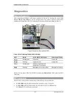
Страница 22: ...ode H 323 MGCP SIP Status Downloader Status Power Steady glow Power OK Power OK Ready Blinking Application OK Loader OK Voice Steady glow Gateway registered with Gatekeeper Call Agent Mngt Blinking Management or voice activity Management activity Besides the four status LEDs the GW 482S includes nine Link Activity LEDs under the RJ 45 connectors SFP Link Activity The SFP Line Activity LED is locat...

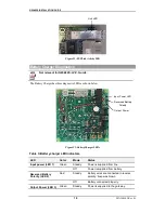
Страница 23: ...rger LEDs Table 3 Battery charger LED Indicators LED Color Mode Status Input power LED 1 Green Steady Power is supplied from line Off Power is supplied from battery Reversed Battery Polarity LED 2 Red Steady Battery wires are connected in reverse polarity Fuse was blown Off Battery connected properly Output Power LED 3 Green Steady Power is supplied to the gateway Rev ersed Battery Polarity Output...

Страница 24: ...aled Operating Temperature 40 C 65 C 13 F 131 F Humidity 10 90 non condensing Dimensions H 13 4 W 14 17 D 6 1 in 34 36 15 5 cm Weight 11 55 lb 5 25 kg Mounting hole positions Vertical distance 14 7 in 373 3 mm Horizontal distance between mounting brackets 6 9 in 175 mm Horizontal distance between drilled holes 5 8 in 245 mm ...

Страница 25: ...box 2 The kit is shipped with the following accessories AS100918 patch card 8 x HR000416 RJ45 to RJ45 cables 4 x HR000415 RJ11 to RJ11 cables 3 plastic tie strips PK000100 pack with screws and washers Patch Panel Installation Instructions 3 Open the Edge Gate cabinet door 4 Disconnect the AC power connector plug 5 Disconnect battery 6 Insert the patch card into the unit 7 Matethe holes onthe Patch...

Страница 26: ...n thetable below see Figure 25 Table 4 LAN Connections between Patch Panel and Gateway Board Connect RJ45 Cables between the GatewayBoard and the LAN ports on the Patch Panel Ethernet Port 1 to L1 Ethernet Port 2 to L2 Ethernet Port 3 to L3 Ethernet Port 4 to L4 Ethernet Port 5 to L5 Ethernet Port 6 to L6 Ethernet Port 7 to L7 Ethernet Port 8 to L8 Figure 25 LAN Connections between the Gateway Boa...

Страница 27: ...482S 4 connect RJ11 cables to P3 and P4 and Phone 3 and Phone 4 respectively Figure 26 GW 482S LAN and Phone Connections 13 Tie wires together usingthe white tie strips for easier access in the future Figure 27 Communications Cablestiedwith Plastic TieStrips RJ 45 LAN connections RJ 11 Phone connections ...

Страница 28: ... in use 3 Ring 4 Tip 5 6 not in use Table 6 10 100BaseT TX Interface Pin to Signal Mapping Pin Signal 1 Rx receive positive 2 Rx receive negative 3 Tx transmit positive 4 not in use 5 not in use 6 Tx transmit negative 7 not in use 8 not in use Table 7 EdgeGate Console Serial Cable VoIP Gatewayside PC side RJ 45 Pin DB 9 Female 3 2 6 3 5 5 ...

Отзывы: