


EV Inverter Operating Manual
___________________________________________________________________________
TECO
– Westinghouse Motor Company 57
Table 13.3
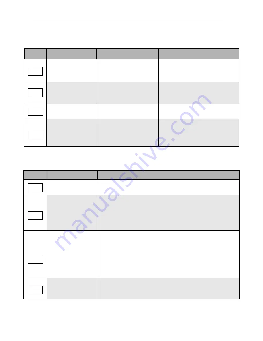
Manually Recoverable Errors Only (no auto-restart)
Display
Error
Cause
Remedy
Overcurrent during stop
1. OC Detection circuit
malfunction
2. Bad connection for CT signal
cable
Send the inverter back for repair
Motor overload
1. Motor under-sized
2. Improper settings of
parameter F43
1. Increase motor capacity
2. Set Parameter F43 based on the motor
nameplate current.
Inverter overload
Excessively loaded
Increase inverter capacity
Undervoltage during
operation
1. Input voltage too low
2. Input voltage varies widely
1. Improve input voltage quality.
2. Set a longer acceleration time
(Parameter F01)
3. Add a line reactor to the input side
4.
Contact technical support
Table 13.4 Set-up Configuration and Interface Errors
Display
Error
Description
Zero speed stop
Set frequency is <0.1Hz. Increase set frequency
Fail to direct start
on power-up
1. If the inverter is set to external control mode (F04=001), and direct
start on power-up is disabled (C09=001), the inverter cannot be
started and will flash SP1 when the run switch is ON and power is
applied. (refer to C09 for selections).
2. Set C09=000 for direct start.
Keypad emergency stop
1. If the inverter is set to external control mode (F04=001) and the
Stop key is pressed, the inverter will stop based on the setting of
F9 and SP2 will flash. Turn the run switch to OFF and then ON
again to restart the inverter.
2. If the inverter is in communication mode and Stop key is pressed,
the inverter will stop based on the setting of (F9) and SP2 will flash.
The PLC or PC must send a Stop command then a Run command
to the inverter for it to be restarted.
External emergency stop
The inverter will decelerate to stop and flashes E.S. when there is
an external emergency stop signal via the Control input terminals
(see parameters F11-F14).
OC
OL1
OL2
LVC
SP2
E.S.
SP1
SP0
Содержание EV INVERTER Series
Страница 69: ......


