background image

MAy-2015

46

– COMMISSIONING THE MACHINE –

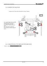
 4.2.6.2 Hub carrier position

WARNING

Accident hazard due to overturning or crushing if the axle is incorrectly positioned! 


When changing the position of the axle or the axle holder, make sure that the machine does not tip over 

(appliance empty, not hitched, boom open).

When it leaves the factory, the axle is located on the chassis to match the chassis variant (narrow or wide) and 

in line with the equipment.
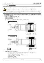
you can change the position of the hub carrier:

• Better tractor trace tracking, 
• Better load distribution,
• If you have to turn the half-axles over to change the ground clearance

wide chassis

narrow chassis

Fig.6 

To change the position of the hub carrier:

1. Place the machine on stands so as to have enough clearance under the wheels.

2. Remove the half-axles (read next paragraph)

3. Remove the four bolts that hold them to the chassis

4. Position the hub carrier in the new position

5. Refit the half-axles and the bolts

6. Remove the stands
7. Check machine balance. 

Содержание VECTIS 1000

Страница 1: ...VECTIS 800e 1000e 1000 1200 Adjustments Use and Maintenance Read carefully before to use the sprayer 990241F Appril 2015 ...

Страница 2: ......

Страница 3: ...YMBOLS 15 3 5 RECOMMENDATIONS PRIOR TO USE 15 3 5 1 User manual 15 3 5 2 Protection of persons 16 3 5 3 Safety and protection systems 16 3 6 RISKS RELATED TO THE USE OF THE MACHINE 16 3 6 1 Hitching the machine 17 3 6 2 Power take off and drive shafts 18 3 6 3 Tyres 18 3 6 4 Braking systems 19 3 6 5 Driving onroads 19 3 6 6 Transport on a truck 20 3 6 7 Before getting off the tractor 20 3 6 8 Othe...

Страница 4: ...ing loading 41 4 1 3 Receipt check 42 4 2 COMMISSIONING 42 4 2 1 Environment 42 4 2 2 Checking the required characteristics of the tractor 42 4 2 3 Qualification of the operator 43 4 2 4 Preparation for assembly 43 4 2 5 Tyres 44 4 2 6 Axles 45 4 2 7 Hitching Uncoupling the machine 47 4 2 8 Installation of the drive shaft transmission 49 4 2 9 Electrical connections 52 4 2 10 Hydraulic assemblies ...

Страница 5: ...king on the circuits 77 5 8 12 Fast stop 78 5 8 13 Rinsing with a cleaning product 78 5 8 14 Rinsing and protecting from frost 79 5 9 PREPARING THE SPRAY MIXTURE 80 5 9 1 Pesticides used 81 5 10 SPRAYER PARTS 81 5 10 1 Main tank spray mixture 81 5 10 2 Rinsing tank 87 5 10 3 Hand wash tank 15 litres 87 5 10 4 Spray pump 88 5 10 5 AUTONET integrated 89 5 10 6 Electric compressor for pneumatic assis...

Страница 6: ...f the sprayer 123 7 1 8 Handling of waste products 123 7 1 9 Air Pollution 123 7 1 10 Rejection 123 7 2 OPERATING CONDITIONS 124 7 3 COMPATIBLE NOZZLES AND FILTERS 124 7 3 1 Nozzle types and sizes 124 7 3 2 Filtering component types and sizes 125 7 4 INSTRUCTIONS FOR MAINTENANCE 125 7 5 TYPES OF PESTICIDES LIKELY TO AFFECT SPRAYER EFFICIENCY 125 7 5 1 Products that may cause failure of the sprayer...

Страница 7: ...AND PLATE NAME of the DEVICE NAME of the EQUIPMENT Frame Number Do not remove the constructor and brand plates from the machine To visualise the positioning of the plate on the equipment and the information concerning the different marking areas refer to chapter MACHINE DESCRIPTION Fig 1 ...

Страница 8: ...May 2015 8 MACHINE IDENTIFICATION ...

Страница 9: ...ld liable for any possible omissions or imprecision 2 2 1 PRODUCT IMPROVEMENTS Tecnoma continuously strives to improve its products and therefore reserves the right to perform the modifications deemed necessary for improvement without prior warning and without being required to perform modifications or improvements on machines or equipment that has already been sold Any modification on Tecnoma mac...

Страница 10: ... illustration 2 of the chapter in question 2 4 EXPECTED USAGE CONDITIONS 2 4 1 MACHINE FUNCTIONS This machine is exclusively intended to be used for current agricultural forestry or wine making activities namely the spreading of phytosanitary products in accordance with environmental regulations Any other use is considered contrary to normal use and is therefore prohibited The consequences of the ...

Страница 11: ...es are made roadworthy under the responsibility of the Authorised Tecnoma Dealer Check that the machine delivered is compliant with the purchase order Read the Operation and Servicing Manual and all Safety Instructions for the machines Insure that the information indicated on the control lists before delivery and upon delivery are thoroughly checked and are compliant before delivering Tecnoma Tech...

Страница 12: ... comply with these rules Can make your machine dangerous It frees the manufacturer of all responsibility in case of damages or injuries If you have doubts please contact your Authorized Dealer Only Authorized Dealers can provide original parts They can assemble the parts and offer advice regarding the assembly and use of these spare parts WARRANTY The start of the guarantee comes into effect on th...

Страница 13: ...mmended Make sure that your tractor is compatible with your machine hitching system maximum admissible hitching load of the tractor sufficient turning angle If your machine is equipped with a steering axle do not exceed its steering angle Only use the machine in forward gears The machine should be driven by just one person sitting in the tractor driver s seat Do not walk on the covers or on any ot...

Страница 14: ...sure with clear water before incorporating products in the tank Read carefully the treatment product manufacturer s label s and follow the instructions therein dosage PPE etc Avoid mixing the products unless their compatibility is specifically recognised by the manufacturer of the phytosanitary products Prevent air from entering the sprayer tank when filling to avoid the formation of foam and prob...

Страница 15: ...itions lead to death or extremely serious injury CAUTION Indicates a low level danger Failure to follow the recommendations could lead to bodily injury and material damage on a reduced or moderate scale IMPORTANT Indicates an obligation Failure to behave properly or to perform the actions described in the recommendations could lead to accidents or malfunction REMARK Indicates information or advice...

Страница 16: ...nels of contamination 3 5 3 SAFETY AND PROTECTION SYSTEMS Before use always activate the safety and and protection systems that must be installed and operational Visually check that these systems are in proper condition on a daily basis It is forbidden to dismantle or to open the protection systems while the sprayer its equipment or its elements are working WARNING A faulty guard or device can be ...

Страница 17: ... lock the hitching device Before setting off check the hitch and make sure that it is properly locked Ö Ö Checks Once the machine is hitched at the front or the back make sure that the hitch does not carry any additional loads and that the weight is properly distributed on the tractor so that it remains stable Make sure the following values are never exceeded total authorised tractor weight author...

Страница 18: ...ommended by the manufacturer Make sure that the universal joint shaft tubes are properly covered when in the work or transport positions Follow the safety instructions of the manufacturer of the universal joint drive shaft Before use check that the transmission shafts are in good working order and that they are correctly assembled and locked Always call on a specialist to solve any problems with t...

Страница 19: ...ad Check the brake system Check the compulsory transport systems lights indicators guards Visually check that all the safety devices are in place particularly those of the towing system Check that the lower hitching arms of the tractor are properly locked Place the machine s pivoting parts in the transport position and lock them with the safety devices provided Lock the 3 point hitching control le...

Страница 20: ... on a slope 3 6 8 OTHER RISKS 3 6 8 1Overhead power lines Make sure that the clearance in relation to the machine is sufficient whenever the machine is operated for example the maximum boom height with the back hatch open Also remember the radio aerial and all other original or other installed accessories If the machine comes into contact with a power line stop the machine and the tractor s engine...

Страница 21: ...ry and alternator as well as all electric equipment or electronic components Avoid the formation of sparks or flames in the vicinity of the battery If the tractor battery needs recharging disconnect all electric and electronic equipment When installing electric or electronic equipment make sure it does not interfere with any of the originally installed systems 3 6 8 7Hydro pneumatic accumulator Th...

Страница 22: ... not certified Once you have finished cleaning the machine Check the fluid circuits and make sure that there are no leaks and that no connections are loose Immediately repair any damage 3 7 2 MAINTENANCE AND REPAIR 3 7 2 1General considerations Maintenance and repair operations must be exclusively performed by qualified personnel Always make sure that the machine and its accessories are kept in pe...

Страница 23: ... has been in contact with liquid fertilizers risk of explosion To remove this risk rinse the parts thoroughly with clean water Before any operations on the electric system disconnect the battery Before all operations on the hydraulic system Make sure that the circuit is not pressurised Eliminate the pressure before disconnecting the hydraulic conduits Do not look for leaks with your fingers Call i...

Страница 24: ...T Check that the warning pictograms are present and clean Replace illegible or missing pictograms by ordering them from your reseller remember to note the reference e g 5319909 You will find the pictogram references used on your machine in chapter MACHINE DESCRIPTION 3 10 1 DESCRIPTION OF WARNING PICTOGRAMS A warning pictogram indicates an area of potential danger on an apparatus as well as the ri...

Страница 25: ...he circuit Pack of valves grouped together with position indicator 4 1 2 CHASSIS Tried and tested robust single one piece chassis 2 versions narrow and wide Polyester paint over a primer coat Stainless steel fasteners Lighting signalling according to current standards 4 1 3 HITCHING BOOM Hitching boom with swivel fork and safety stop hitch on lift arm Shaft support Stand 4 1 4 AXLE 2 axles square ...

Страница 26: ...t volute outlet High resistance HLE steel column Driven pulley with 24 teeth Rated speed 4000 rpm Detachable ventilation via direct locking clutch Active belt tension automatically with lever activated gas cylinders on bearings Lubrication oil bath lubricated bearings with gauge 4 1 9 COMPATIBLE BOOMS 4 1 9 1 Booms for pneumatic equipment Ö Ö Basic equipment 2M 4D 2M 2D 4C diameter 120 S 17 VITIFI...

Страница 27: ...haft 143218M Extra for wide angle shaft Brace for articulated boom for fruit farmer tractor Pulley for 29 hp power to replace 35 hp Step for 856e and 1056e in series on 1056 and 1256 Boom options Hydraulic lift for VITIFIX and VITISIT II requires an additional hyd SE Hydraulic lift for manual VITIMOBIL requires one additional hyd dual control 2 TELESITs for adjusting the locations electrically Red...

Страница 28: ...1 Wheels 10 75R15 3 for 1000 and 1200 1 Wheels 31x15 5 15 for 1000 and 1200 1 Axle support sheath for wide rim for 1056 and 1256 Max permissible rim 1480 mm Stand on wheels Articulated boom Also order wide angle shaft 143218M Extra for wide angle shaft Brace for articulated boom for fruit farmer tractor Step for 856e and 1056e in series on 1045 and 1245 Boom options SV block for PréciJet 6 sides 4...

Страница 29: ...er weight WEIGHT ON AXLE 5 MAX PERMISSIBLE WEIGHT 2000 WEIGHT ON RING 6 MAX PERMISSIBLE WEIGHT 783 YEAR 7 DATE MACHINE WAS MANUFACTURED MAX P 8 MAX PRESSURE OF MACHINE S SPRAYING CIRCUIT DEPEN DING ON THE CASE 1 2 3 4 5 6 8 7 VE1 XXX YY VE1AAAAAA CHAMPAGNE ARDENNE 15 2014 NOTE For DREAL approval The PTAC values the weights on the axle and the ring correspond to those on the approved machine machin...

Страница 30: ...rk station valve pack pos2 driving position closed cab pos1 work station valve pack pos2 driving position closed cab ventilation disenga ged engaged disenga ged engaged disenga ged engaged disenga ged engaged acoustic pressure Db weighted A 92 94 b b a a b b max value acoustic pressure Db weighted C 94 94 5 b b a a b b Measurement conditions coupled to the tractor no a no a on bench yes a yes a wo...

Страница 31: ...hing device in case of separation of the hitch The second hitching device must take the form of a cable sling C C Fig 4 WARNING Risk of an accident following separation of the machine from the tractor Systematically secure the hitch by attaching the safety cable to the tractor such that it does not obstruct the universal joint shaft Make sure that the cable sling and its attachments are in good co...

Страница 32: ...TRIBUTION OF LOADS A B Fig 5 08E 800 narrow 25 KPH PTAC 1990 kg A 783 KG B 2000 KG 10E 1000 narrow 25 KPH PTAC 2200 kg A 783 KG B 2000 KG 10L 1000 wide 25 KPH PTAC 2220 kg A 783 KG B 2000 KG 12L 1200 wide 25 KPH PTAC 2490 kg A 783 KG B 2000 KG ...

Страница 33: ...e machine s max W width is 2 55 meters Fig 6 W The machine s max L length is 4 37 meters The machine s max H height is 2 90 meters The following height must be added the radius of the type of wheel chosen in the machine s configuration if the axle is inverted add 0 2 meters the lowest wheel L H Fig 7 ...

Страница 34: ...a VITIVARIO boom a VITIVARIO boom PRECIJET a VITIVARIO GV boom STANDARD PRECIJET 2 60 VITIVARIO GV boom LONG PRECIJET a max H Fig 8 a to be defined 4 4 4 TANK CHARACTERISTICS Filling capacity with water Machines Main tank Rinsing tank Hand wash 800 narrow 800 litres 80 litres 15 litres 1000 narrow 1000 litres 80 litres 15 litres 1000 wide 1000 litres 120 litres 15 litres 1200 litres 1200 litres 12...

Страница 35: ... Spain 1 2 support plates with rear lights stop lights and turn indicators 2 Registration plate light 3 Location of the identification plate 4 4 Triangular red reflectors 5 Maximum permitted speed 25 km h Fig 9 1 1 2 4 4 4 3 4 5 4 4 6 CHARACTERISTICS OF THE PUMPS AND OTHER COMPONENTS Refer to chapter USING THE MACHINE ...

Страница 36: ...rols 11 Rinsing tank 12 Rinsing tank tube gauge 13 Front left hydraulic agitator 14 Hand wash tank 15 Wheel and tyre on adjustable axle in position 16 Mud guard option Fig 12 30 23 25 26 29 17 Access cover to mixer and LAV BOX options 18 Main tank top opening cover 19 Electrical connection box 20 Distribution 21 Vent 22 shield 23 intermediate shaft 24 Access to declutching device 25 Valve assembly...

Страница 37: ...AYING COMPRESSION DISC COMPRESSION DISC SPRAYING PRESSURE GAUGE DISC REGULATION VALVE VITITRONIC VALVE DISCHARGE B AUTONET BUILT IN OPTION VALVE 3 bar G H PRESSURE GAUGE SUPER FILTRATION OPTION 15 10 OUTLETS 18 10 PRECIJET 15 10 OUTLETS 18 10 PRECIJET 4 7 SAFETY PICTOGRAMS The warnings and pictograms on the machine provide indications of the safety measures to be observed and help prevent accident...

Страница 38: ...sequences if the instructions to avoid the risk are not respected 3 Instructions to avoid the risk Attention Ne pas oublier de remplir le lave mains d eau propre Warning Do not forget to fill the hand wash tank clean water Achtung Vergessen Sie nicht den Handwaschbehälter mit sauberem Wasser zu füllen SP I RU CZ BG NL RO 5319936 Attention Lavez vous les mains Caution Obligation to wash your hands ...

Страница 39: ...Risks of fingers or hand cutting Wait for complete standstill Gefahr von Schnittverlet zungen an den Fingern oder der Hand Warten Sie bis zum voll ständigen Stillstand Riesgo de cortes en los dedos o la mano Espere a la parada total Rischi di tagliarsi e dita o la mano Attendere il completo arresto Respecter le sens et la vitesse de rotation de 540 t min Observe the direction and speed of rotation...

Страница 40: ...May 2015 40 DECRIPTION OF THE MACHINE ...

Страница 41: ...volved at a safe distance 4 1 2 UNLOADING LOADING 4 1 2 1On a loading bay or with a truck with booms IMPORTANT Follow the instructions when coupling the machine tractor Only use a that has the required power as described in the prior conditions conditions Remove the tie downs and transport chocks Fig 2 1 Fig 1 Fig 2 IMPORTANT If the machine is unloaded with a crane use the attachment points identi...

Страница 42: ...ICS OF THE TRACTOR DANGER A tractor that is not suitable can create risks of instability when loaded handling and insufficient braking problems as well as risks of breakages Check that the tractor meets the required standards Carry out a braking test to ensure that the tractor provides the statutory deceleration power even with the machine coupled carried The requirements for the tractor concern i...

Страница 43: ...a person qualified to carry out the operations listed in chapter COMMISSIONING THE MACHINE IMPORTANT Before commissioning the machine the user must first read and understand the instructions 4 2 4 PREPARATION FOR ASSEMBLY WARNING Risks of accidents due to impacts crushing cutting jamming and seizure in the zone where the hydraulic or electrical parts operate Do not block the controls on the tracto...

Страница 44: ... first 20 hours of use then twice a year 4 2 5 4Disassembly 1 Slightly lift the machine using a jack located under the hub carrier 2 Remove the nuts from the transportation wheels 3 Remove the wheels 4 2 5 5Tyre inflation pressure IMPORTANT Depending on the type of tyre fitted to your towed sprayer please comply with the inflation pressures shown in the table below and corresponding to the wheels ...

Страница 45: ...360 1000 2410 1200 2630 Max admissible loads Variants kg on the axle 2000 on the trailer hitch 825 4 2 6 AXLES 4 2 6 1Axle specifications IMPORTANT Vectis axles are designed for use at 25 km h Fig 5 C o hang F F F F F F CAUTION Apply a tightening torque F of 135 Nm to the bolts and lock nuts that retain the axles Check the tightening torque after the first 20 hours of use then twice a year Axles M...

Страница 46: ...row or wide and in line with the equipment You can change the position of the hub carrier Better tractor trace tracking Better load distribution If you have to turn the half axles over to change the ground clearance wide chassis narrow chassis Fig 6 To change the position of the hub carrier 1 Place the machine on stands so as to have enough clearance under the wheels 2 Remove the half axles read n...

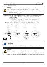
Страница 47: ...n their mounts so that the square is located at the desired height 180 at the lowest to obtain a clearance of 500 mm 90 towards the rear or 270 towards the front to obtain a clearance of 400 mm Check the balance of the machine and if necessary move the axle holder forward or backward 5 Retighten the bolts B 6 Remove the stands Fig 7 B 4 2 7 HITCHING UNCOUPLING THE MACHINE IMPORTANT During Coupling...

Страница 48: ...low all of the movements of the machine without tension or rubbing 4 2 7 1Moving the stand Read the Stand paragraph in chapter USING THE MACHINE of this manual 4 2 7 2Hitch IMPORTANT Connect the flexible hydraulic feed hoses before coupling the machine 1 Position the lower arms B of the hydraulic raiser substantially at the same height as the coupling rods A of the sprayer hitch 2 Move the tractor...

Страница 49: ...rive shaft and place it on its support 4 Disconnect the electrical lines 5 Remove the safety pins from the coupling shafts 6 Uncouple the ball joints from the tractor arms 7 Disconnect the hydraulic hoses and store them on the support provided 4 2 8 INSTALLATION OF THE DRIVE SHAFT TRANSMISSION WARNING Risk of accidents due to Projection of damaged and or destroyed parts if the drive shaft is compr...

Страница 50: ...nly actuate the 3 point hydraulic coupling commands from the work station provided for this purpose Do not remain between the tractor and the machine IMPORTANT The recommendations of the transmission manual must be respected 4 2 8 1Preparation Couple the machine to the tractor do not couple the drive shaft Apply the hand brake ...

Страница 51: ...s to a length A 150 mm IMPORTANT The shortest length must be obtained when the drive shaft is horizontal The longest length must be obtained when the drive shaft is completely raised Deburr clean the tubes and cover with grease 9 Refit the guards 10 Refit the drive shaft to the tractor and the machine taking care to comply with the direction of assembly tractor side of the drive shaft 11 Check tha...

Страница 52: ...tation made by the Tecnoma authorised distributor Install the control unit on its mount 4 2 9 2Connecting the unit or the handle in the cab Connect the one or more wiring harnesses Fig 16 4 2 9 3Connecting the optional VITITRONIC DPAE regulator wiring harness Connect the harness to the control unit Fig 17 4 2 9 4Highway lighting 1 Connect the 7 pin male plug to the 7 point female plug on the tract...

Страница 53: ... hydraulic functions are supplied by the hydraulic circuit on the tractor DANGER Danger of accidents due to crushing Accidental lowering of the raised machine via the hydraulic circuit of the tractor REMARK All of the hydraulic pipes can be identified they have one or several coloured rings close to their end that can be connected to the tractor s distributors 4 2 11 CONNECTING THE HYDRAULIC FUNCT...

Страница 54: ... The maximum admissible pressure in the free return oil circuit is 10 bar If the hydraulic circuit of the tractor has the centre open place the hydraulic unit in the centre open mode To switch the unit to centre open mode open the valve on the side of the block Loosen the valve knob 1 completely If the hydraulic circuit of the tractor has the centre closed place the hydraulic unit in the centre cl...

Страница 55: ... engine remove the key from the ignition 5 If you have to park on a slope use the chocks 4 3 ADDITIONAL DOCUMENTS IMPORTANT Read the additional instructions with the manual of your machine 4 3 14 1For regulation systems 99990 REGULAIR regulation only EN or 990244 VITITRONIC regulation only EN 4 3 14 2For the equipment 99920 VITIFIX booms or 99721 VITIMOBIL booms or 99722 VITISIT booms or 990237 VI...

Страница 56: ...the first time with phytosanitary products Rinse the circuit completely Remove the nozzles Unscrew the plugs on the ends of the pipes Fill one fifth of the volume of the tank with water Spray read the USING THE VALVES paragraph in chapter USING THE MACHINE Remove and clean the filters Refit the plugs onto the ends of the pipes Fit the nozzles ...

Страница 57: ...tor that is not suitable can create risks of instability when loaded handling and insufficient braking problems as well as risks of breakages Respect the maximum loads of the machine and the thrust loads on the tractor WARNING Risk of crushing due to Accidental movement of the tractor and the machine Lowering of the raised machine Before entering the danger zone between the tractor and the machine...

Страница 58: ... of the danger zone In case of danger stop the tractor s engine immediately WARNING Phytosanitary products health risks in case of accidental contact It is compulsory to comply with the manufacturer s indications to use these products in a safe way avoiding all contact with skin eyes and mouth You must wear Gloves and overalls that are resistant to chemical agents Waterproof safety footwear Face p...

Страница 59: ...x actly aligned to the tractor s RMP counter CHECKING THE TRACTOR SPEED 100 m To do so 1 Measure and mark a distance of 100 metres 2 Engage the selected speed 3 Set the PTO rotating at exactly 540 rpm 4 Using a stop watch record the time t in seconds required to travel the 100 metres 5 Calculate the actual speed V in km h V 360 t The table below shows the times t to travel 100 metres and the equiv...

Страница 60: ...d jaw directly onto the pump shaft until it locks 5 3 2 COUPLING THE DRIVE SHAFT WARNING Risk of crushing and impacts due to a lack of space between the tractor and the machine when coupling the drive shaft Connect the drive shaft before coupling the machine to the tractor 1 Move the tractor back to leave around 25 cm between the tractor and the machine 2 Immobilise the tractor to avoid any accide...

Страница 61: ...shaft 5 4 OPERATING PRINCIPLE OF THE SPRAYER The electrically controlled distribution the solenoid valves control the LH and RH spray feed individually or simultaneously by means of switches on the handle or control housing The spray pump 1 via the filter 2 and the multi channel suction valve A sucks according to the layout of the valves the spray mixture of the main tank 3 the clean water of the ...

Страница 62: ...NG TANK ACCESSORY VALVE C LAV TON x2 FRONT AGITATOR REAR AGITATOR REAR AGITATION VALVE E FRONT AGITATION VALVE D ACCESSORY SUCTION A AUTONET OPTIONAL Fig 2 PUMP DECOMPRESSION TAB DECOMPRESSION TAB PUMP PRESSURE GAUGE TAB REGULATION VALVE VITITRONIC ACCESSORY BACKFLOW B AUTONET INTEGRATED OPTIONAL VALVE 3 bar G H PRESSURE GAUGE SUPER FILTRATION OPTIONAL 15 10 GUNS 18 10 PRECIJET 15 10 GUNS 18 10 PR...

Страница 63: ...n operating position Suction selector valve G Control valve for the hopper rinsing gun H Control valve for the LAV BOX R Valve controlling tank returns from decompressions A Suction valve B Control valve for incorporation or LAV TON washers C Accessory valve Regulation activation D Control valve for the front agitation E Control valve for the rear agitation F Eductor accessory valve ...

Страница 64: ...suction from the main tank suction neutralised 5 6 2 VALVE FOR OUTPUT TO LAV TON EDUCTOR OR ACCESSORY Ö Ö Valve B LAV TON incorporation accessory 5 6 3 ACCESSORY VALVE REGULATION ACTIVATION Ö Ö Valve C closed max pressure regulation position accessory feed 5 6 4 VALVE CONTROLLING TANK RETURNS FROM DECOMPRESSIONS Ö Ö Valve R open closed ...

Страница 65: ...t agitation 1 2 3 1 tank full front and rear agitation open D and E 2 under 500 litres in the tank only open rear agitation E 3 tank empty close agitation open closed Valve E rear agitation open closed 5 6 6 EDUCTOR ACCESSORIES VALVE Ö Ö Valve F F Fig 10 open closed ...

Страница 66: ... To open the rinse water supply to the hopper turn the valve by a quarter turn Valve H Supply to the LAV BOX in closed position To open the rinse water supply to the LAV BOX turn the valve by a quarter turn H G Fig 11 5 7 MAIN FUNCTIONS THAT ARE POSSIBLE 1 Incorporation 2 Spraying 3 LAV TON 4 Spray gun 5 Accessories 6 Rinsing ...

Страница 67: ...by the product maker then finish up by filling the main tank To fill the tank open the rear mixture tank lid To open the eductor cover turn it towards the left and lift it Fig 12 5 8 1 2Filling the rinsing tank WARNING Contamination of the rinsing tank is not allowed by phytosanitary products or the spray mixture Only fill the rinsing tank with clean water never with phytosanitary products or the ...

Страница 68: ...ctive gloves and clothing see paragraph Personal protection in chapter GENERAL SAFETY IMPORTANT Throw the soluble plastic product sachets directly into the spray mixture tank via the access hole whilst running the agitation 5 8 2 1From the eductor option To access the eductor hopper Open the front mixture tank cover To open the eductor cover turn it towards the left and lift it Remove the red plug...

Страница 69: ...e that it is incorporated Fig 16 1 Note that as soon as there is nothing left to incorporated immediately close valve B to avoid sucking in air and thereby forming foam in the tank As soon as incorporation is finished rinse the hopper using the rinse hose T Open tap G Fig 17 5 8 2 2From the eductor optional using water from the rinsing tank REMARK It is possible to incorporate phytosanitary produc...

Страница 70: ...en rear agitation E 5 8 3 ADJUSTING SPRAYING IMPORTANT Refer to and comply with the tables for flow rate calculations in the equipment instructions when setting spraying 5 8 4 SPRAYING IMPORTANT Check the sprayer by calibrating it Before starting a spray campaign In case of differences between the spray pressure effectively displayed and the spray pressure required as listed in the spray chart IMP...

Страница 71: ...nitary product used for the treatment Consult the Spraying tables in the boom instructions Take additional measures to avoid drift when the wind speed reaches 3 m s and 5 m s do not spray REMARK When the average wind speed is over 5 m s the leaves and branches move IMPORTANT The spray mixture tank is empty when the spraying pressure clearly drops off suddenly If the pressure drops when the tank is...

Страница 72: ... Machine without compressor after removing the cap from the air valve V on the air cushion regulator decompress it by pressing it 2 Close the spraying solenoid valves using the control handle read instructions on how to use the control handle 3 Set the PTO to idle V Fig 20 P 4 Place the valve handles in the positions shown 2 5 Open the spraying solenoid valves using the control handle Spraying sta...

Страница 73: ...nce speed Refer to the control unit instructions and Calibrate the flow meter if there is a difference between the effective flow rate and the flow rate displayed Calibrate the advance sensor pulses per 100 m if a difference is observed between the effective advance and the advance displayed 5 8 5 RINSING THE SPRAY MIXTURE TANK USING THE LAV TON WASHERS ATTENTION Risk of damaging the LAV TON washe...

Страница 74: ...gaging the ventilation 1 Using the electrical control close all of the solenoid valves 2 Place the valve handles in the positions shown 4 3 Set the PTO speed to between 200 and 540 rpm Fig 23 4 4 Open the hand spray gun circuit from the tap Z located at the rear of the sprayer 5 Use the spray gun Fig 24 Z REMARK The rinsing tank empties in approx 1 minute 5 8 7 RINSING THE HOPPER AND THE PACKAGING...

Страница 75: ...s the spray mixture concentration The rinsing tank empties in approx 1 minute IMPORTANT Carefully rinse the empty drums of the products ensure they cannot be re used bring them together and dispose of them in compliance with the recommendations Do not re use them If you only have the spray mixture to rinse the preparation tank with then first perform preliminary cleaning with the spray mixture To ...

Страница 76: ...ntrol unit or using the control handles open all of the sections Spraying starts 5 Spray in the field while driving Fig 28 6 IMPORTANT Once is complete switch quickly to agitation see next paragraph ATTENTION Never close the sections before stopping the PTO REMARK The rinsing tank empties in approx 1 minute 5 8 9 AGITATION OF THE SPRAY MIXTURE TANK IMPORTANT We recommend placing the spray mixture ...

Страница 77: ... Positioning of the valves Valves A B and F Suction from rinsing use function 3 in the table label Check the presence of a minimum amount of water in the rinsing tank Suction from the mixture tank use function 2 in the table label Valve C set the handle in line with function 4 in the table label see opposite 2 Run the PTO to between 200 and 540 Fig 30 5 8 11 CLEANING THE SPRAYING FILTERS AND WORKI...

Страница 78: ...remove the deposits of products The use of a specific cleaning product may be recommended by the manufacturers of phytosanitary products IMPORTANT Procedure Rinse the sprayer with clean water in the field with the main tank empty by diluting the used volumes of spray mixture and spray onto the parcel that has just been treated Clean the sprayer with the cleaning product in a suitable area away fro...

Страница 79: ...ank read the paragraph on draining the spray mixture tank Draining the tank Fig 33 Remote emptying REMARK To better drain the spray mixture tank switch off tank bottom agitation 3 Remove and clean the filters and nozzles separately in a solution of the cleaning product 4 Cleaning the outside of the machine Refer to the paragraph Cleaning the outside of the sprayer 5 8 14 RINSING AND PROTECTING FRO...

Страница 80: ...ts in case of accidental contact with phytosanitary products and or the spray mixture Incorporate the phytosanitary products into the main tank with the eductor optional Do not prepare the spray mixture close to fountains or surface water Avoid any leaking of contaminants through appropriate behaviour To forewarn against any danger for third parties do not leave the phytosanitary products the prep...

Страница 81: ...tions of the product manufacturer 5 9 1 PESTICIDES USED REMARK Use the page PERSONAL NOTES at the back of this booklet to list the pesticides used 5 10 SPRAYER PARTS 5 10 1 MAIN TANK SPRAY MIXTURE WARNING Risk of accidents in case of accidental contact with the spray mixture Risks of pollution in case of overflow via the filling hole When filling to overflow and on steep slopes ...

Страница 82: ...x2 8 Rear agitation 9 Remote emptying 10 Main suction 11 Tank return lines from decompression 12 Empty tank switch 13 Internal cleaning LAV TON x2 14 LAV TON feed 15 Gauge 5 10 1 1Cover of the spray mixture tank cover of the eductor DANGER Risk of poisoning due to toxic vapours Do not go inside the spray mixture tank To open the cover turn it to the left and lift it up To close the cover push it d...

Страница 83: ...s linked to the density of the spray mixture It may not be possible to completely fill the tank DANGER Risks of accidents following situations of unstable driving Never exceed the maximum loading allowed on the axles and the wheels IMPORTANT Check the tank connectors and flexible hoses for leaks Correct position of all the control parts Never leave the sprayer unsupervised when filling REMARK A hi...

Страница 84: ...ater supply This can avoid any discharge or return of the spray mixture into the drinking water supply Fix the end of the flexible filling hose within 10 cm above the opening of the spray mixture tank This clearance will offer maximum safety to avoid any pollution of the drinking water supply 5 10 1 4Via the access hole IMPORTANT Respect the regulations in force when filling the spray mixture tank...

Страница 85: ...ump is started Starting agitation is triggered by the valves D and E located on the front face of the machine Read the paragraph on Agitating the mixture tank in this chapter Fig 38 D E 5 10 1 6Draining the spray mixture tank WARNING Risk of accidents in case of accidental contact with the spray mixture Always wear gloves WARNING Risks of pollution to ground during draining Ensure that the spray m...

Страница 86: ... correct operation of the sprayer Perfect spray mixture filtration considerably influences the success of the phytosanitary measures Respect the approved combinations of filters or the mesh sizes Remember that the use of filter cartridges of 80 or 100 meshes inch can cause on certain phytosanitary products filtration of the active materials Check for each product with the manufacturer of the phyto...

Страница 87: ...tion connector Filling capacity with water Machines Rinsing tank 800 narrow 80 litres 1000 narrow 80 litres 1000 wide 120 litres 1200 litres 120 litres The overflow capacity is at minimum 5 of the nominal capacity 5 in compliance with standard ISO FDIS 4254 6 1 2 3 Fig 44 4 5 4 Fig 45 IMPORTANT Only fill the rinsing tank with clean water Label 5319936 4 4 5 10 3 HAND WASH TANK 15 LITRES WARNING Ri...

Страница 88: ...A Every 200 hours or at the end of the spraying season change the oil in the pump Fill up slowly while rotating the shaft by hand this bleeds off the air PROBLEM CAUSE REMEDy The pump doesn t suck water One or more valves are seating improperly Examine the valve seats and clean them Pressure gauge fluctuates badly The pump is sucking air or air has not been entirely bled from the pump Check the su...

Страница 89: ...he quantity of water that has flowed depends on adjustable timing If AUTONET rinsing of just the boom the quantity of water transferred is measured by a flow meter The transfer valves are motorised valves that open simultaneously One allows the pump to suck clean water from the rinsing tank and the other to supply the LAV TON wash ers in the tank The LAV TON washers thus supplied rinse the walls a...

Страница 90: ...UAL VOLUME UPON COMPLETION OF WORK 5 LITRES 10 LITRES RINSING 1 1 16TH 25 25 25 50 50 50 RINSING 2 75 15 8 157 31 15 RINSING 3 15 8 31 15 RINSING 4 8 15 TOTAL VOLUME FOR DILUTION 1 100TH 103 55 49 207 112 95 49 95 The higher the number of rinsing cycles the less the total volume of clean water consumed is important Once the cycle is finished spray the diluted product and start a new dilution cycle...

Страница 91: ...ON Risk of pollution Emptying the bottom of the tank is prohibited in case of Frozen ground Snow covered ground Steeply sloped ground Permeable ground Ground with shrinkage cracks Periods where there is saturations of water Periods of rainfall 5 10 5 3Maintenance Fitting the empty tank sensors CAUTION Risk of the AUTONET not operating If a tank sensor is changed respect the direction of assembly ...

Страница 92: ...LECTRICO ELEKTRISCHE DRUCKFERNVERSTELLUNG 3653 7 TX REGULAIR 47449 41750 51477 35988 30021 38325 38473 48902 37868 37868 54297 901272 900653 901447 900988 50853 M B M O B N VJ M 3643 3 B Bleu Blue Azul Blaü M Marron Brown Moreno Braün N Noir Black Negro Schwarz O Orange Naranja VJ Vert jaune Green yellow Verde amarillo Grün gelb 5429610 5429617 5429612 5429613 5429614 5429616 5429615 5429618 54296...

Страница 93: ...CTRO MAGNET The needle guide screw A fig 4 should not be tight else reduce the outer diameter of guide screw at B with Emery paper WATERTIGHTNESS of NEEDLE on its SEATING Check condition of both conical head of needle and of seating fig 4 point C Check that there is play between base of needle and the top guide screw at D fig 4 ROUTINE SERVICING OF ELECTRO MAGNET Make sure that the coil slides eas...

Страница 94: ...ou 48196 rouge Replacer la rondelle fendue 47772 Remettre le capuchon noir 42296 DEPANNAGE MANUEL En cas de mauvais fonctionnement de l électro vanne celle ci restant fermée retirer le capuchon rouge 42296 et dévisser l écrou 37611 pour soule ver le noyau par l intermédiaire de la rondelle fendue 47772 CONNECTION Remove black cap P N 42296 Remove disc P N 47772 Remove black hood P N 48675 or red h...

Страница 95: ...etract the step lift the step 1 fold the step back to the vertical position until it locks Fig 49 B 5 10 11 THE SAFETY OF THE AUTOMATIC COUPLING WARNING There is an accident hazard if the machine and trac tor become separated Always secure the hitch by attaching the safety cable C to a solid part of the tractor and so that it does not interfere with the drive shaft Ensure that the sling and safety...

Страница 96: ...ncompatible drive shaft Only use a wide angle drive shaft IMPORTANT We strongly recommend turning with the PTO disengaged REMARK The machine s turning radius depends on the tractor hitch used 5 10 13 1Adjustments Ö Ö Longitudinal draw bar adjustment It can be set to a second position by removing the shafts A A Fig 51 B B G Ö Ö Draw bar hitching bar positions The machine s turning radius can be red...

Страница 97: ... hitch arms to separate the stand from the ground 2 Remove the pin 2 and remove the locking shaft 3 Remove the stand from the draw bar Store the stand on its holder 3 Fit the shaft and the pin 4 Ö Ö Fitting the stand BEFORE UNHITCHING THE MACHINE Remove the stand from its holder 3 1 Remove the pin 4 and remove the locking shaft 2 Remove the stand Fit the stand onto the draw bar 1 1 Insert the stan...

Страница 98: ...ne to the hydraulic circuit of the tractor Under no circumstances must mineral oils be mixed with vegetable oils Respect the maximum hydraulic fluid pressure of 200 bar Ensure that the hydraulic connectors are clean when they are connected Engage the hydraulic connectors into the sleeve s until the connector s click s into place 1 Move the control lever on the distributor to the level of the tract...

Страница 99: ...pull the handle and rotate it counter clockwise to bring the handle to position B 2 Gently release the handle 3 The dog clutch has reached its end of travel Turn the handle again counter clockwise until the dog clutch engages 4 Release the handle 5 Secure the access to the dog clutch by refitting the cover 2 using the nut 1 Fig 55 1 2 3 Ö Ö The dog clutch is moved from engaged position C to diseng...

Страница 100: ... dust cover tubes 1 must be screwed in place Any emulsion caused by water in the bearing voids the warranty If water bubbles appear in the tubes stop and always drain immediately Never shorten the two vent tubes Fig 60 On starting do not worry that oil will rise in the tubes as this is normal If the oil level falls stop and check for any leaks After use do not worry about any difference in the col...

Страница 101: ...in chapter GENERAL SAFETY REMARK When travelling between the farm and the field to be treated and to ensure the spray mixture is homogeneous 1 Switch on the PTO 2 Set the circuit to spray mode function 2 of the table label 3 Open the agitation 5 12 STOPPING THE MACHINE 5 12 18 1Normal stopping 1 Stop the PTO 2 Close the valve A see opposite Fig 61 3 Close the valve F 5 12 18 2Emergency stop 1 Swit...

Страница 102: ...r filter cartridge flexible suction hose Remove the blockage The pump is sucking air Check the flexible suction hose connectors for leaks special equipment on the suction connector No flow from pump Suction filter filter cartridge dirty Suction filter clean the filter cartridge Valves seized or damaged Replace the valves The pump is sucking air air bubbles can be seen in the spray mixture tank Che...

Страница 103: ...NING Danger of accidents due to crushing shearing cutting wrenching getting run over tearing catching and electrocution in the following instances Accidental lowering of the raised machine via the hydraulic three point coupling circuit of the tractor Accidental lowering of raised and non fixed elements of the machine Accidental starting and movement of the tractor and machine assembly Immobilise t...

Страница 104: ...ircuit can penetrate the skin and cause serious injuries as well as intoxication The works on hydraulic circuits must only be assigned to specialists with appropriate training Before performing work on the hydraulic circuit make sure that the installation is not under pressure Eliminate the pressure before disconnecting the hydraulic hoses Only use the proper tools when looking for leaks Do not lo...

Страница 105: ... storage DURING APPLICATION IMPORTANT If unused for a short period Set the pump in motion with the circuit off mixing IMPORTANT If unused for a long period Do not leave the spray mixture in the tank After EACH USE Check that the tank is totally empty Proper calibration of the sprayer will enable you to obtain a minimum quantity of spray mixture in the tank once you have finished the treatment Pour...

Страница 106: ...year Empty your pump by referring to paragraph your machine maintenanceSDSq Clean the sprayer thoroughly use a cleaning product approved for your material Make sure all bolts are tight Check the joints of the nozzles the anti spill systems and all filters We recommend the application of an external protection product particularly on all metal parts of the sprayer and boom See details below Check t...

Страница 107: ...dding anti freeze If your boom is equipped with AGP allow the liquid to circulate in the boom for a few minutes Then spray the liquid until the entire boom sprays the coloured liquid for a few seconds If your boom is not equipped with AGP spray the liquid until the entire boom sprays the coloured liquid for a few seconds you can recover the remaining product by draining the main tank Do not empty ...

Страница 108: ...age consumption 1 litre for 15 m After 48 hours apply paint 1st coat diluted by 10 2nd coat undiluted CAUTION please comply with all instructions shown on the product packaging MAINTENANCE AND PROTECTION PRODUCTS Tecnoma offers you an entire range of products that are perfectly suited for your sprayer Name Code 2 litre sample pack 9512401 Litest box 25 9513901 Rustol Minium 1 litre can 901334 Spra...

Страница 109: ...there is one Inside the tanks inner surfaces decantation trap agitation system suction system draining gauge filling sieve rinsing system LAV TON etc None of these should contain deposits The state of the induction bowl its mixing system its hopper rinsing system its phytosanitary product packaging rinsing system its pipework The accumulation of powders requires careful cleaning The hydraulic cont...

Страница 110: ...o make sprayer operation easier Take care to ensure that this operation is as short as possible for example by cleaning the sprayer every day once spraying has been completed The spray must not remain unused in the tank it must not for example remain in the tank overnight The life and reliability of the sprayer is largely determined by the time the phytosanitary products are in contact with the ma...

Страница 111: ...aph VALVE UTILIZATION of chapter USING THE MACHINE CAUTION Clean with high pressure or vapour do not direct the jet towards electrical hydraulic compressed systems nor towards motors hydraulic hoses joints filling caps etc keep a reasonable distance of approx 300 mm between the cleaner and the machine ...

Страница 112: ...May 2015 112 MACHINE MAINTENANCE ...

Страница 113: ...draw bar and its sling safety cable assembly and its attachment points The condition of the wheels and hubs check the pressure of the tyres the tightening of the wheel bolts grease the hubs The oil levels pump transmission systems The condition of the transmission belt 6 5 2 GREASING VECTIS Carefully clean the lubrication points and the grease pump before lubrication Remove the old grease and repl...

Страница 114: ...pped 6 5 3 1Lower and upper bearings Ö Ö LOWER BEARING IMPORTANT For all work on the lower bearing please refer to your Tecnoma Approved Distributor Ö Ö UPPER BEARING UNTIL APRIL 2015 Check by unscrewing the caps 1 at the top of the level tubes if the holes are not obstructed 2 If water bubbles appear in the tubes stop and always drain immediately Drain the bearing once a year or every 50 hours in...

Страница 115: ...visually inspect the outside and the inside of the belt C replace it as soon as the first signs of deterioration appear Fig 64 C Ö Ö Removing the belt To replace the belt order tool No 95236 1 Remove the rear cover 2 Remove the disengaging support D by removing the four screws and their washers Fig 65 D 3 Fit the tool O 4 Tighten the upper nut on the tool E until the belt can be removed 5 Remove t...

Страница 116: ...slotted into the upper and lower pulley grooves 13 Slacken the nut E on the tool until the gas cylinders tighten it 14 Once the tool is free remove it 15 Refit the engaging mount 16 Refit the rear cover onto the Vectis 6 5 4 HYDRAULIC AND SPRAY CIRCUITS 6 5 4 1Check After the first 10 hours of service then every 50 hours of service 1 Check all of the circuit components for leaks 2 If required tigh...

Страница 117: ...5 AXLES IMPORTANT Have your axle assembly serviced regularly by a trained specialist 6 5 6 TYRES Do not work on tyres unless you have the required tools and experience If in doubt consult qualified personnel CAUTION Incorrect assembly can seriously jeopardize your safety IMPORTANT The installation of tyres other than the ones recommended by the manufacturer is not allowed IMPORTANT Regularly check...

Страница 118: ...iter USING THE MACHINE to position the valves so as to secure the circuit 6 5 7 1Suction filter Clean the suction filter every day in compliance with the label opposite code 36737 1 1 Drain the filter using the red cap 2 the filter flap closes 2 Remove the lower part of the filter 3 3 Remove and clean the filter cartridge 4 Fig 67 1 2 4 3 2 6 5 7 2Pressure gauge filter To access and clean the filt...

Страница 119: ...aph in chapter USING THE MACHINE 6 5 9 SERVICING THE SPRAY PUMP 6 5 9 1Accessing the pump To remove the pump 1 Remove the drive shaft 2 Remove the suction and waste pipes 2 3 Remove the mounting bolts from the mounts that hold the pump onto the chassis 3 4 Remove the filter mount 5 Slacken the clamp on the pump shaft 6 Pull the pump out towards the front Fig 69 1 2 3 6 5 9 2Draining the pump To dr...

Страница 120: ...ves or valve seats faulty or dirty Clean or Replace D Air intake for suction Seal Irregular pressure Uneven flow rate Valves or valve seats faulty or dirty Clean or Replace D Noisy pump Low oil level Strangled or obstructed suction Check suction Presence of water in the oil One or more damaged membranes Replace the damaged membrane s D CERTAIN OPERATIONS MUST BE PERFORMED By A PROFESSIONAL COMPLy ...

Страница 121: ...ray mixture in chapter VII MACHINE USE of this manual 7 1 2 TANKS FILLING WARNING Danger of ground pollution during filling Never leave the sprayer unattended 7 1 3 SPRAYING PREPARATION WARNING Danger of ground pollution during preparation of the spray mixture Do not prepare the spray mixture near fountains or surface water Avoid all contaminating product leakage by adopting suitable behaviour Dur...

Страница 122: ...oom instructions Select the required nozzle size before starting the spray process by referring to the spray table bearing in mind the expected advancement speed the required flow rate and the desired spray pressure Select a slow advancement speed and a weak spray pressure to avoid undue spray drifting IMPORTANT Read the paragraphs about adjusting and using the sprayer in chapter VII MACHINE USE o...

Страница 123: ...gislation when disposing of waste especially when working on hydraulic and lubrication systems cleaning with solvents Waste retrieval Do not mix fuels and oils Recover drained liquids in clean and sealed containers specific for this purpose Avoid the use of food and beverage containers Return your worn batteries and accumulators It is forbidden to stock abandon or dump tyres in the natural environ...

Страница 124: ...rking condition Use and clean the filtration systems Thoroughly clean your sprayer before using a different phytosanitary product Rinse the spray circuit for every nozzle change IMPORTANT To reduce the risk of drifting Spray early in the morning or late in the evening there is generally less wind at this time of day Use anti drift nozzles Maintain a precise boom height the close the line of the no...

Страница 125: ...here are discrepancies between the spraying pressure actually displayed and the required spray pressure according to the spray screen IMPORTANT Refer to paragraph GENERAL CHECKS in chapter VII MACHINE USE 7 4 INSTRUCTIONS FOR MAINTENANCE IMPORTANT Read the paragraphs regarding daily maintenance periodical inspections and wintering in section OVERALL SPRAYER MAINTENANCE in chapter VIII MACHINE MAIN...

Страница 126: ...fter treatment Your machine is compatible with the use of liquid fertilizers The sprayer s pump membranes have been designed by Tecnoma and are resistant to a wide range of products If you have doubts please contact your Authorized Tecnoma Dealer 7 6 PESTICIDES USED COMMENTS Use the page of chapter PERSONAL NOTES at the end of this booklet to note the pesticides used 7 7 CONNECTION AND USE OF EQUI...

Страница 127: ...ramp sprayer section Fig 1 Fig 2 1 2 3 Connect the pressure gauge 2 4 Start the spraying operation in order to check the pressure 1 Stop spraying 2 Remove the plug 1 from the end of the section chosen for the check 7 9 2 PRESSURE MEASUREMENT IN HYDRAULIC OIL SYSTEM DEPEND OF YOUR MACHINE To measure hydraulic system pressure Fig 3 Fig 4 3 3 1 Remove the plug 3 from the hydraulic unit 2 Connect the ...

Страница 128: ...May 2015 128 ENVIRONMENTAL PROTECTION ...

Страница 129: ...May 2015 129 Chapter 8 8 PERSONAL NOTES ...

Страница 130: ...May 2015 130 PERSONAL NOTES ...

Страница 131: ...5 127 GAUGE 25 36 83 GENERAL CHECKS 59 GENERAL MAINTENANCE 105 GROSS PERMITTED LADEN WEIGHT 29 31 32 GUARDS 18 H HANDLE 61 HANDLES 69 72 73 74 75 76 HAND WASH 87 HANDWASH 25 HARNESS 52 HAZARDOUS AREA 9 HEIGHT 124 HITCH 47 48 60 61 114 HITCHING BOOM 25 36 HOOKING POINTS 41 HOPPER 63 66 68 69 70 74 75 77 80 HOSES 21 22 23 104 110 111 124 HUB 113 HYDRAULIC 13 16 17 19 20 21 23 43 48 51 53 54 98 101 1...

Страница 132: ...IEVE 82 SINGLE ACTION 53 54 SLEEVE 67 84 86 SLIDING 43 SOLENOID VALVE 26 27 SOLENOID VALVES 26 53 61 72 74 75 77 93 119 SPEED 11 17 18 19 22 35 71 72 73 102 122 124 SPRAYER 10 14 16 20 22 29 33 44 48 49 53 57 58 59 61 67 70 73 74 78 79 80 83 84 86 87 88 95 103 104 110 111 114 121 122 123 124 125 126 127 SPRAY GUN 74 77 80 SPRAYING 121 122 STAND 48 49 113 STAND 25 36 48 49 114 STRAINER 25 SUCTION F...

Страница 133: ... 33 0 3 26 51 18 38 Spare Parts information Tel 33 0 3 26 51 18 55 Fax 33 0 3 26 51 18 38 order deadlines Tel 33 0 3 26 51 18 77 Fax 33 0 3 26 51 18 38 Website www tecnoma com E mail tecnoma tecnoma com SAS Tecnoma Technologie au capital de 1 174 400 euros N siren 350 484 309 RCS Reims B 350 484 309 N identification TVA FR 02 350 484 308 APE 2830 Z ...

Отзывы: