AutoGRAPH ON-BOARD CONTROLLER • USER MANUAL
42
TechnoKom © 2016
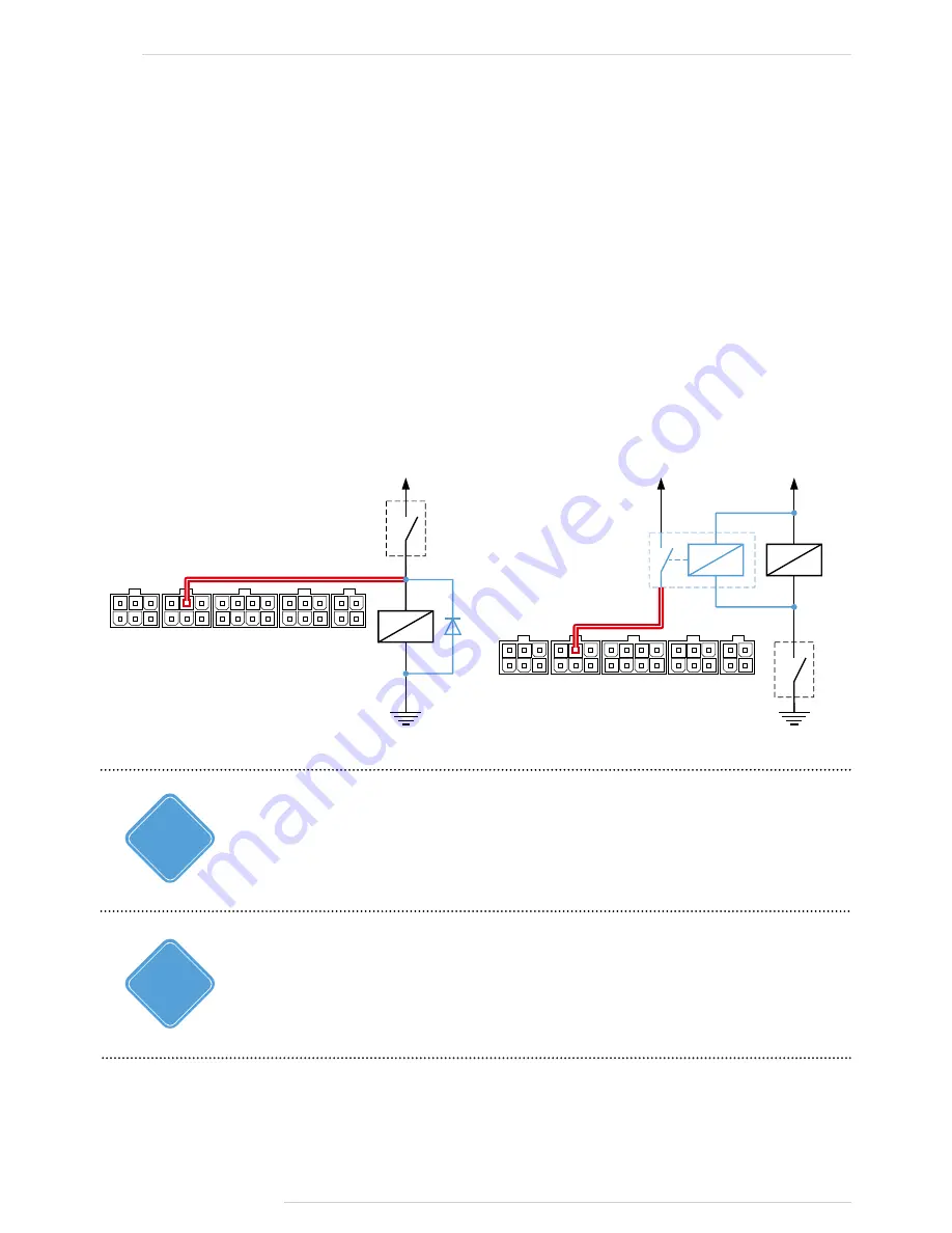
Connection Diagram for Active High Digital Input Inductive Load
Circuit:
Sometimes, it is necessary to integrate the controller’s digital input into a circuit with
an inductive load such as a relay winding, solenoid valve or any other device, which has
inductance coil.
When an inductive load is being disconnected, stored current must be dissipated, this causes
a self-induced electromotive force of inversed polarity (back EMF) that may damage the
controller.
To prevent such breakdown, use one of the following protection options, if an inductive load
is being applied to the tracker:
1. Protective diode
(fig. 1) – to be installed in parallel to the inductive load. In this case,
forward current of the protective diode (I
fw
) should be at least 1.5 • I
holding, coil
. If the coil
holding current is unknown or uncertain, use the option with safety relay protection.
2. Safety relay
(fig. 2) – to be installed in parallel to inductive load. In this case, the
safety relay contacts are used for closing the controller’s input on supply voltage.
PR
O
TEC
TIVE DIODE
RELAY or OTHER
INDUCTIVE LOAD
LIMIT SWITCH,
SENSOR or BUTTON
INPUT 8 - RED with WHITE STRIPE (19)
+V
+V
SAFETY RELAY
RELA
Y or O
THER
INDUC
TIVE L
O
AD
LIMIT SWIT
CH,
SENSOR or BUT
TON
INPUT 8 - RED
with WHITE STRIPE (19)
+V
Fig 1.
Fig 2.
You may use following protective diodes: KD212, KD116-1 or similar.
Use may use safety relays designed for switching of direct current circuits with voltage rating
compatible with the vehicle system voltage. For example, relays of 901.3747 type manufactured by
AVAR, AO, (www.ellink.ru/co/avar) for a vehicle system voltage of 24 V.
i
NOTE
i
NOTE


