background image

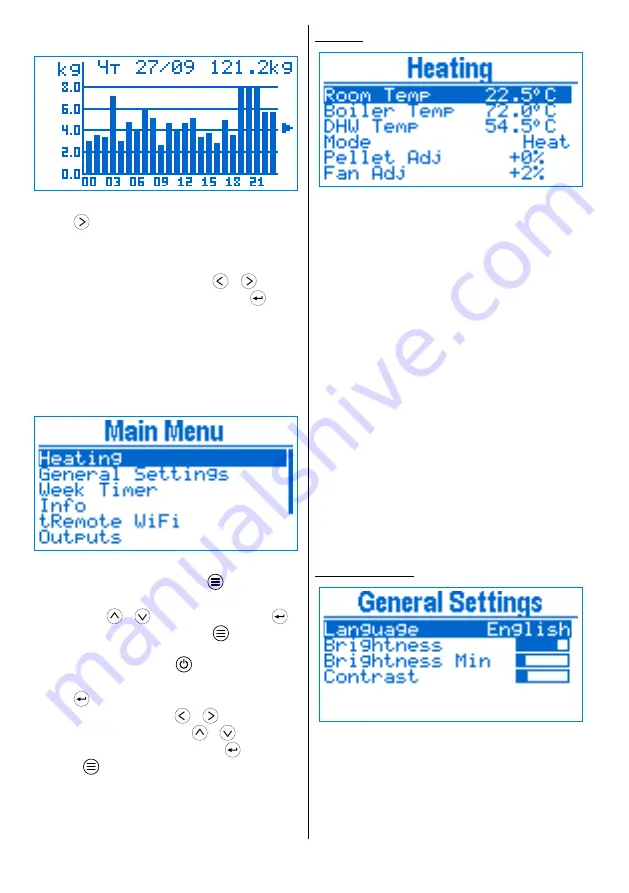
Fuel consumption

Fig 6

Fuel consumption

Press 

 from Main screen to see information 

regarding the fuel consumption. From the sub-menu 
you can choose to access per day or per month 
statistic. A graphic shows the consumed pellets for 
every day / month. Use the buttons 

 / 

 to 

select a particular period and press button 

  to 

switch do detailed view. In daily mode a chart per 
hour is shown, as in monthly mode per day. The top 
part of the detail view displays date / month 
selected, as well as the total fuel consumed for the 
particular period.

Main Menu

Fig 7

Main menu

From main screen, press button 

 to enter the 

main menu.

Use buttons 

 / 

 to navigate and button 

 to

select the current menu item. Press 

 in order to go

back one level, from the main menu you go back to 
the main screen. The button 

 takes you directly to 

the main screen.

Press 

 to edit a parameter. In edit mode the 

parameter value blinks. Use 

 / 

 to increase / 

decrease the value by 1 unit, or 

 / 

 to change 

by 10 units. When done editing, press 

 to save the 

change or 

 to cancel the modification and revert 

to the previous value.

Heating

Fig 8

Heating

Boiler Temp

 – boiler temperature set point. 

The power is modulated in order to achieve the 
temperature set point.

DHW Temp

 – DHW temperature set point.

Mode – 

device heating mode.

Heat 

– just the main heating is working 

and its temperature is monitored

DHW

 – just the DHW heating is working and 

the DHW temperature is monitored

Heat+DHW 

– both heating circuits are 

active

DHW+Heat 

– both heating circuits are 

active, as the DHW one is with higher priority. 
When the DHW pump is running, the main one 
is stopped.

Pellet Adj

 – adjusts the fuel quantity that is 

being fed, depending on the fuel quality. The quantity
is increased or decreased in percents of the nominal 
quantity.

Fan Adj

 – adjust the fumes fan relative to the 

service settings.

The parameters shown in the menu, depend on the 

device configuration.

General Settings

Fig 9

General settings

Language 

– user interface language

Brightness 

– set the display brightness in 

active mode.

Brightness Min 

– set the display 

brightness in idle mode. Idle mode occurs when 60 
sec have passed since the last button press.

Using the device

5

Содержание tPell

Страница 1: ...tPell Pellet Combustion Controller Version 24 06 20...

Страница 2: ...tings 5 Week Timer 6 Info 6 Outputs 6 Date Time 7 Errors Actions 7 Principle of operation 8 Work mode 8 ON AUTO 8 OFF 8 States 8 Clean 8 Ignition 8 Kindle 8 Burn 8 Purge 8 Shutdown 9 Wait 9 Service pa...

Страница 3: ...mostat on or off if used Current temperature the measured temperature of the heated object Power the current operating power when burning in kW or relative units Fumes fan revolutions of the fan in Fe...

Страница 4: ...In AUTO mode the temperature is fixed by the week timer or the external thermostat Quick menu Fig 5 Quick menu To access the Quick menu press the button from the Main screen For navigation use the but...

Страница 5: ...press to save the change or to cancel the modification and revert to the previous value Heating Fig 8 Heating Boiler Temp boiler temperature set point The power is modulated in order to achieve the te...

Страница 6: ...decrease increase the temperature by 0 5 C as with by 2 C Info Fig 11 Information On this screen usage information is displayed Pellet counter for the pellets burned from the last reset In order to re...

Страница 7: ...creen title in brackets Errors 6 the number of the registered errors is shown Press over selected element to get detailed information about it To switch between views use the buttons Errors The error...

Страница 8: ...by monitoring the temperature of flue gases or the flame intensity depending on configuration On successful ignition it passes to the next state If the ignition time runs out before ignition is detec...

Страница 9: ...e state However the device will automatically transition to ON mode when the system needs to generate heat The device is in standby awaiting for some of the heated objects to need heating When all the...

Страница 10: ...pause Feeder run All parameters listed below that set the feeder time have the meaning of Feeder Fan Max Maximum revolutions per minute of the fumes fan It is used to calculate the percents that set...

Страница 11: ...Turn on temperature Pump Min Temp Pump Hyst Turn off temperature Pump Min Temp Pump Hyst Wait DHW ON Temperature difference below the set temperature in order to exit from Wait state Wait DHW OFF Temp...

Страница 12: ...e specified the shutdown is started Wait Temp ON Difference between the current and set temperature under which the device immediately transitions from Wait to Burn state Wait Temp OFF Difference betw...

Страница 13: ...ignition Exceeding this temperature raise is considered for successful ignition Light Level Light sensor level exceeding it is considered for successful ignition Feeder2 Secondary feeder work time in...

Страница 14: ...alue of the parameter is OFF Purge Period Purge period When the device is in Burn state and the set time expires it transitions to Purge state Upon completion it returns back to Burn state The minimum...

Страница 15: ...ted and saved After changing the service password you will be asked again for it in order to access the service menu Stop Work Fig 18 Stop Work The device can be forced to stop ignoring the conditions...

Страница 16: ...g stopped In Burn state a loss of flame is detected according to the flue gases temperature or light intensity Power failure The power was cut for time exceeding the recovery time Feeder blocked The c...

Страница 17: ...ture sensor room temperature thermostat NTC 10K t4 Temperature sensor DHW Light sensitive i1 Light sensor flame intensity Active level GND i2 Hall sensor for fan revolutions counting i3 Capacitive ind...

Страница 18: ...Fig 20 Connection 18 Connection...

Страница 19: ...h square opening sized 128 x 57 mm To mount the controller first unscrew the mounting bracket then put the controller in the opening Fix it in place by putting the bracket on the back side and fasten...

Страница 20: ...term is 24 months from date of sale The guarantee is not valid in following cases Incorrect installation Attempts to make repairs and or modifications of equipment by the customer Visible damages of...

Отзывы: