4. speCIfICaTIons
Input Ports
4×HDMI, 4xVGA, 4xRCA, 1×RS-232,
1xRJ-45(Control), 5×IR INPUT, 4xAudio
Output Ports
4×HDMI, 4xIR OUTPUT
Input Resolutions Support
Up to 1920x1080P@60Hz
Output Resolutions Support
Up to 1920x1080P@60Hz
Control
IR , RS-232 , TCP/TP, Buttons
ESD Protection
Human-body Model:
± 8kV (Air-gap discharge)
± 4kV (Contact discharge)
Power Supply
12 V/2.5 A DC (US/EU standards,
CE/FCC/UL certified)
Dimensions
440mm (W)×200mm (D)×44.5mm (H)
Weight
2380 g
Chassis Material
Metal
Silkscreen Color
Black
Operating Temperature
0 ºC~40 ºC/32 ºF~104 ºF
Storage Temperature
−20 ºC~60 ºC/−4 ºF~140 ºF
Relative Humidity
20~90 % RH (non-condensing)
Power Consumption
13.5 W(Max)/1.2W(Standby)
5. panel funCTIons
5.1 front panel
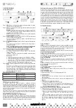
Part 1. lCM: Displays the information of each input and output setting and
EDID management.
Part 2. Ir: IR Receiver window (accepts the remote control signal of this
device only).
poWer: Press this button to power the device on/off. The LED will
illuminate green when the power is on, red when it is in ‘Standby’
mode.
loCK: Press this button to lock all the buttons on the panel, press
again to unlock.
Part 3. ouTpuT/InpuT: Press the OUTPUT and INPUT button to select the
output corresponding input.
For example: Press OUPUT ALL>INPUT 1, The OUTPUT A,B,C,D will be
set to INPUT 1.
Part 4. picture adjust: Press the button to adjust the output picture.
for example: press output 1>sCaler, The output 1 video will be
scaler adjust.
note: 1. scaler adjust the step: six steps.
2. The auTo adJusT button only work on VGa input.
Part 5. sources input select and mode select:
1. Press the button to select source input.
For example: Press input 1>VGA, The input 1 will be select the VGA
video input.
2. Press the button to select mode, select matrix, multi-viewer and
video wall.
For example:
a. Select matrix mode, press buttons HDMI/M1 > ENTER.
b. Select multi-viewer mode, press buttons VGA/M2 > ENTER, and
press buttons A/B/C/D select different mode
c. Select video wall mode, press buttons CV/M1 > ENTER, and press
buttons A/B/C/D select different input.
Part 6. edId: Smart EDID management, the LCM will display the EDID
operation.
Press the MENU button will enter the EDID management window,
press UP or DOWN button to select the needed EDID setting, press
ENTER button to select the download input source. It can easy
download any EDID mode to any input source.
Note: The EDID mode table
EDID Mode
EDID Description
1
1080i, 2CH AUDIO
2
1080p, 2CH AUDIO
3
DVI 1920X1080
edId. What is it and what is it used for?
Under normal circumstances, a source device (digital and analog) will require
information about a connected device/display to assess what resolutions
and features are available. The source can then cater its output to send
only resolutions and features that are compatible with the attached device/
display. This information is called EDID (Extended Display Information Data)
and a source device can only accept and read one EDID from a connected
device/display. Likewise, the source an only output one resolution for use by
a connected device/display.
Why is edId so important with the hdMI Matrix ?
The Matrix is complex piece of technology that replicates and switches
between multiple inputs and outputs. Each connected source device will
require one EDID to read. EDID management is carefully handled by HDMI
Matrix to provide a single EDID for each source to read.
What options do I have to manage the edId in the hdMI Matrix ?
First, it is important to note that each source device can only output one
video/audio signal type. This includes resolutions and timings. When multiple
devices/displays are used, such as with the HDMI Matrix, it is important to use
devices/displays that have similar or compatible resolutions/features. This
will ensure that the single video/audio signal produced by the source device
is accepted by all of the connected output devices/displays. The user has the
option, through the EDID management window, to choose how the unit will
manage the EDID from multiple HDMI devices/displays. Therefore the user
has some control over the resolutions/features that the source devices will
output. The HDMI Matrix for has a multiple EDID management modes that
will control how the EDID information from multiple devices/displays are
combined, ignored, and routed.
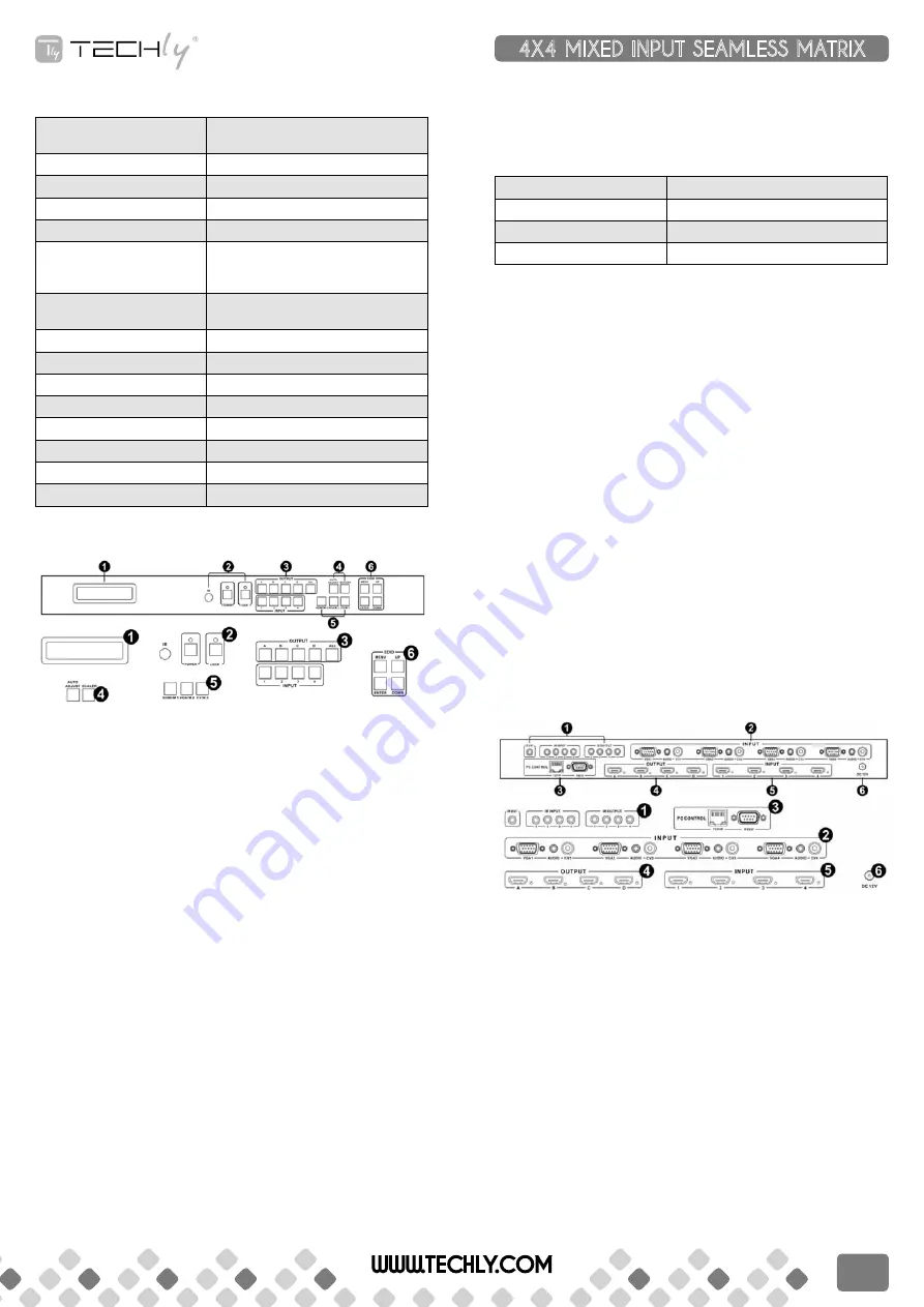
5.2 rear panel
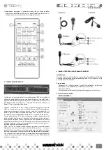
part1: Ir Channel
Ir eXT: if the panel sensor is obstructed or the unit is installed in a closed
area out of infrared line of sight, the IR RX receiver included can be inserted
into the IR EXT port at the rear to extend the IR sensor range and enable local
control of the matrix.
Ir In/ouT: Super IR control system interface. For further details, please refer
to the Super IR system control introduction.
part2: VGa CV and audIo InpuT
Connect to the VGA or CV input source devices such as a DVD player, a Set-
top Box or PC with VGA cable or RCA coaxial cable.Each VGA or CV input is
accompanied with a 3.5mm stereo audio input.
part 3: pC ConTrol
TCp/Ip: This port is the link for TCP/IP controls, connect to an active Ethernet
link with an RJ45 terminated cable.
rs232: Connect to a PC or control system with D-Sub 9-pin cable for the
transmission of RS-232 commands.
part 4: ouTpuT
The HDMI OUTPUT connect to HDMI equipped TVs.
WWW.TECHLY.COM
4X4 MIXED INPUT SEAMLESS MATRIX
QUICK INSTALL GUIDE
7
Содержание IDATA HDMI-MX944
Страница 12: ...12 WWW TECHLY COM ...


