4-2
EM18-33017
4.1 CUTTER DRIVE (CUTTER MODE)
4. MECHANISM DESCRIPTION
4.1.1
Replacing the Cutter Arm and Clutch
If a moving portion of the arm or the clutch is distorted by wear, purchase the following part from
TEC Parts Dept. and replace them. Doing so will prolong the cutter life.
Part No.:
ZBA-1464001
Part Name: Arm and Clutch Kit
NOTES: 1. Apply grease when replacing the parts. (Refer to Fig. 2-17)
2. Cutter unit components except above are unavailable.
3. Please purchase 10 sets or more at one order.
■
Replacing procedure
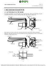
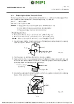
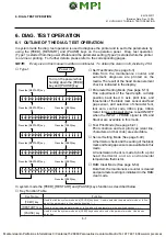
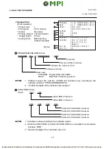
1. Remove the P-4x12 screw to detach the arm. (Refer to Fig. 4-2)
2. Remove the S-3x4 screw to detach the clutch. (Refer to Fig. 4-2)
NOTE:
When removing the S-3x4 screw, use a straight hex wrench.
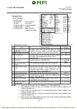
3. Secure the new clutch with the S-3x4 screw so that the screw is perpendicular to the section
of the D-cut power shaft of the cutter motor.
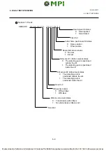
4. Turn the power on and move the clutch to the home position.
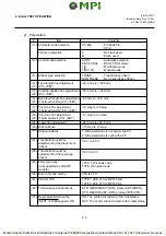
5. Insert a 2.8 mm thick clearance gauge between the fixed and rotary cutters (right end) and
secure the new arm with the P-4x12 screw. A clearance gauge must be made of plastic or
something which will not damage the cutter edge.
90
°
S-3x4
Clutch
D-cut power shaft of
the cutter motor
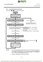
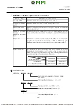
6. Activate the cutter and check that the clutch is in the home position (indicated by the following
figure). If it is not, do over from step 3.
35
°
- 45
°
Clearance Gauge
(t=2.8 mm)
Fixed Cutter
Rotary Cutter
Fig. 4-3
Fig. 4-4
Fig. 4-5
Clutch

