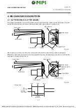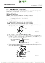
3-5
EM18-33017
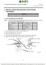
3. INSTALLATION PROCEDURE FOR OPTIONAL EQUIPMENT
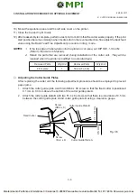
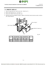
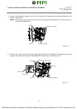
9) Mount the operation panel and the left side cover on the printer.
10) Close the top and right covers.
11) Refer to Section 6.4 of the Maintenance Manual to load the label and make a test print to check
forproper strip issue. If not, refer to Section 6.3.2 of the Maintenance Manual to adjust the strip
position.
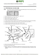
CPU PC Board
Screw (FL-4 x 6)
Screw (FL-4 x 6)
PWM PC Board
Strip Harness
CN2
Strip Base
Opening
Screw (FL-4 x 6)
Strip Unit
Strip Sensor Harness
Strip Harness
CN15
CN12
Fig. 3-7
n
o
i
t
p
i
r
c
s
e
D
t
i
n
U
/
y
t
'
Q
t
i
n
U
p
i
r
t
S
1
s
s
e
n
r
a
H
p
i
r
t
S
1
3.3 STRIP MODULE (B-4908-H-QM)
3.3 STRIP MODULE (B-4908-H-QM)
NOTE:
This module cannot be used together with the B-4208-QM cutter module. Remove the cutter
module if it has been attached to the printer.
1) Open the right side cover and the top cover. (See Fig. 2-1)
2) Remove the left side cover (See Fig. 2-1)
3) Remove the front plate (See Fig. 2-6)
4) Remove the operation panel (See Fig. 3-1)
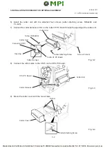
5) Connect the strip harness to the CN2 on the PWM PC board through the opening of the strip base.
6) Install the strip unit to the printer with the four FL-4 x 6 screws removed in STEP 3.
7) Connect the strip harness to the CN15 on the CPU PC board.
8) Connect the strip sensor harness to the CN12 on the CPU PC board.


