background image


11 

4.


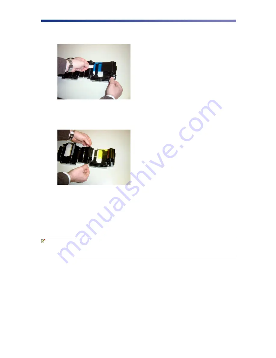
Remove the tape and pull the released ribbon towards the take up bobbin.  Attach the tape 
to the bobbin making sure the ribbon is centered on the bobbin. 


5.


Advance the takeup bobbin 2-3 turns to verify that the ribbon is properly seated on the 
bobbin and all slack has been removed from the ribbon. 


6.


Close the ribbon cartridge and slide the release lever to the right ensuring the cartridge is 
securely locked. 

7.


Slide the ribbon back into the printer and lower the green retaining lever to lock the 
ribbon cartridge in place. 

8.


Close front access panel. 


Note


Store ribbons in a cold, dark place.  Maximum storage period is 6 months after 
delivery if they are kept in an environment of 25º C (77º F), 50% RH.  Beyond 
this time frame, print quality may be affected.  


Figure 2-10:  Remove tape 

Figure 2-11:  Advance bobbin 

Содержание Nisca PR5300

Страница 1: ...ad Somerset NJ 08873 Copyright 2007 Kanematsu USA Inc All rights reserved Revision date July 10 2007 TEAMNisca and the TEAMNisca logo are a registered trademark of Kanematsu USA Inc Microsoft and Wind...

Страница 2: ......

Страница 3: ...B Connection 14 2 5 Loading Cards 15 2 6 Card Thickness Adjustment 16 2 7 Turning On the Printer 17 2 8 LCD Modes of Operation 17 2 8 1 Normal Mode Information 17 2 8 2 User Mode Information 17 2 8 3...

Страница 4: ...Map C 1 PR5300 PR5310 User Mode Menu Map 41 C 2 PR5350 User Mode Menu Map 43 C 3 PR53LE User Mode Menu Map 45 Appendix D Parts Replacement D 1 Replacing the Input Rollers 47 D 2 Replacing the Print H...

Страница 5: ...is printer produces cards ideal for driver s licenses printing bureaus access control badges and standard corporate identification 1 3 About This User s Guide This User s Guide contains important safe...

Страница 6: ...ning Do not spill liquids on the printer Always prevent debris from entering the printer Do not place heavy objects on the printer Use only a power source indicated in the Electrical Requirements sect...

Страница 7: ...nal injury could result The printer must be connected to a grounded electrical power supply and properly protected against electrical surges and grounding faults 1 5 2 Physical Requirements The PR53xx...

Страница 8: ...models will be specified 2 1 Printer Features 2 1 1 Front of the Printer A Front Access Panel Opens to allow access to the inside of the printer B Front Access Panel Release Button Button that allows...

Страница 9: ...terface Connection Available Interface Connection Refer to Appendix A C Options Connector Port The printer supports the attachment of an optional card lamination module Options connector port not avai...

Страница 10: ...ower LED Indicates the power is on E Ribbon Change Menu Button Normal User Press this button to change the ribbon Press and hold this button enter User s Mode Use this button for menu selections F Cle...

Страница 11: ...requirements as stated above Caution IMPORTANT The printer must be placed on a level surface in a dust free environment It is essential to be able to access the printer from all sides for its installa...

Страница 12: ...contact your authorized reseller Note Keep all packing material in case you need to move or re ship the printer 4 Remove all packing tape 5 Open the front access panel by depressing the release button...

Страница 13: ...e available ribbon types Ribbon Type PR5300 PR5310 PR5350 PR53LE K KO YMC YMCK YMCK02 YMCK03 3BP YMCK0K2 Note IMPORTANT Nisca card printers require special ribbons to function properly For this reason...

Страница 14: ...to press the Ribbon Change button for initial setup To load the ribbon follow these steps 1 Open the ribbon cartridge by sliding the release lever to the left 2 Remove new ribbon from its packaging a...

Страница 15: ...Close the ribbon cartridge and slide the release lever to the right ensuring the cartridge is securely locked 7 Slide the ribbon back into the printer and lower the green retaining lever to lock the...

Страница 16: ...SCSI connection obtain the appropriate interface cable Note Use only an external DB25 to 50 pin high density half pitched Amphenol connector TEAMNisca recommends an Adaptec ACK D2H 1M ICE 1 Make sure...

Страница 17: ...e in the Off position If the printer is at the end of the chain then the terminating switch should be set to On 7 Insert the power cord into the power receptacle on the rear of the printer Plug the ot...

Страница 18: ...computer 4 Insert the power cord into the power receptacle on the rear of the printer Plug the other end into an available wall outlet 2 4 3 USB Connection To connect the printer to your computer obt...

Страница 19: ...the card surface as dirt from your hands could impair the print quality 3 Holding the stack of cards by their edges place the cards into the card feeder between the guides 4 Always load cards with the...

Страница 20: ...on the adjustable gate 3 Insert a card into the card feeder just under the gate 4 Lower the gate until it slightly touches the card 5 Raise the gate one half the thickness of the card and tighten the...

Страница 21: ...ed the green Ready indicator light will be illuminated The LED lights work in conjunction with the printer s LCD panel to help communicate the status of the printer The printer will stay in this mode...

Страница 22: ...g The Ribbon on page 9 Setting the appropriate ribbon type is required for proper operation SCSI ID Select Select the appropriate SCSI ID See Chapter 2 4 1 SCSI Connection on page 12 ROM Version Optio...

Страница 23: ...o on to have card with error re outputted Parallel Print Set to on to process multiple cards simultaneously Card Eject Face Select which side of the card to eject Print Area Select printable area on t...

Страница 24: ...minimum cleaning requirement schedule CLEANING SCHEDULE CLEANING TOOL Takeup Roller 10 000 prints Alcohol Swab Input Rollers 2 000 prints Alcohol Swab Card Flip Turn Transport Rollers 10 000 prints A...

Страница 25: ...nce 3 Open the card feeder door and remove any blank cards 4 Remove the protective paper backing from both sides of the cleaning card 5 Insert the Cleaning Card into the feed gate until the card stops...

Страница 26: ...ain the best print quality 1 Open the card feeder door remove any blank cards and locate the takeup roller 2 Use an alcohol swab to clean the roller Use your fingertips to move the roller back and for...

Страница 27: ...an the rollers with an alcohol cotton swab in the direction pictured 4 Once the dust and debris is cleaned from the rollers place the input roller module back into the printer Push in until it hits th...

Страница 28: ...rn transport roller 180 by moving the unit counter clockwise 3 Advance the green knob and use an alcohol swab to clean the rubber and white plastic rollers 4 After cleaning the flip turn transport rol...

Страница 29: ...ard where color was not transferred or every 2 000 prints to maintain a consistent print quality To clean the print head you will need a print head cleaning pen available from your authorized reseller...

Страница 30: ...tridge 2 Power off the printer and remove the power cord 3 Open the front access panel by depressing the release button Lift the green retaining lever and remove the ribbon cartridge 4 Using a phillip...

Страница 31: ...ter Occasionally new firmware versions are released which have updated and or new features New firmware updates can be downloaded from the Nisca website at www teamnisca com and loaded into your print...

Страница 32: ...date your firmware 1 Download and install the Firmware Update Utility from www teamnisca com 2 Run the firmware update program The firmware update utility program will appear 3 From the download utili...

Страница 33: ...e update process that will only take a few minutes 6 Click end to exit the program and turn the printer power off for a few seconds and back on You may verify the status of the new firmware version by...

Страница 34: ...4 1 Interpreting General LCD Messages LCD SCREEN MESSAGE PROBABLE CAUSE ACTION Initializing The printer is performing an internal test before use Wait for the Ready to Print message Ready to Print Th...

Страница 35: ...Mode on the printer and change the settings in the Ribbon Type sub menu to match the ribbon type installed in the printer i e YMCK YMCKO YMCKOK etc Ribbon Wind up miss The ribbon is not installed cor...

Страница 36: ...nce the card in a position easier for removal If this error occurs again clean the rollers in the flip turn unit Card Jam Print Area A card is jammed between the flip turn unit and the print unit Pres...

Страница 37: ...CAUSE ACTION Color discoloration Color Drop Most likely due to debris on the card dust inside the printer or dirty rollers Ensure cards free of debris Ensure printer is in a clean area Clean all rolle...

Страница 38: ...y the correct ribbon is specified in the printer settings Unexposed dark area appears on the printed image Material or debris is on the card Try another card and use only cards specified by your autho...

Страница 39: ...ic key while the computer is booting up This key will differ depending on which brand of computer you have but is often specified on screen during initial startup For example a line such as Press DEL...

Страница 40: ...36 4 6 PR53xx Series Block Diagram Flip Turn Feeder Print Unit Encoder Figure 4 1 Series block diagram...

Страница 41: ...Card PVC or polyester cards with polished PVC finish Medium Size Card width length CR 80 2 125 54mm x 3 375 85 6mm Card width length CR 79 2 051 52 1mm x 3 303 83 9mm Medium Thickness 0 020 20mil to...

Страница 42: ...1mm x 331mm Weight 28 6 lbs 13 kg Operating Temperatures 65 to 80 F 18 to 27 C Power Source 100 240 Volts AC 50 60 Hz auto switching Agency Listing UL CE FCC Driver Compatibility Microsoft Windows War...

Страница 43: ...P P E N D I X B Printer Configuration ITEM NAME DESCRIPTION A Card Feeder The cards automatically feed from off the bottom of the stack The slot is 1 5 times the thickness of the card to A B C D E F...

Страница 44: ...it and is pressed against the surface of the card E Print Head The component of the printer that actually does the printing This component is fragile and must not be bumped or touched with anything ot...

Страница 45: ...stment Yellow Adjustment Printer Ribbon Ribbon Selection Image Setup Black Print Mode High Speed High Quality Magenta Adjustment Return to Normal Mode Error Buzzer On Off Image Data Print Cyan Adjustm...

Страница 46: ...election Main Program Setup Data Reset Finish Return to Normal Mode Encoder Type Lo Co High Co Head Code Return to Normal Mode Encode First On Off Encoder Unit Return to Parent Encode Mode Card side s...

Страница 47: ...bbon Selection Total Count Black Print Mode High Speed High Quality Magenta Adjustment H Roller Ribbon Image Setup Gamma 0 Select Cyan Adjustment Return to Normal Mode Error Buzzer On Off Sharpness Ad...

Страница 48: ...set Finish Return to Normal Mode Exe Key Print On Off Head Code Number Return to Normal Mode Print Retry On Off Serial Number Return to Parent Menu Parallel Print On Off Encoder Unit Card Eject Face U...

Страница 49: ...ter Ribbon Ribbon Selection Image Setup Gamma 0 Select Magenta Adjustment Return to Normal Mode Error Buzzer On Off Sharpness Adjust Cyan Adjustment Return to Parent Menu Ribbon Type Image Data Print...

Страница 50: ...emove Normal Cards Printer Status Entry Base Program Set Cleaning Card Please wait Now Cleaning EXE Key Print On Off Main Program Return to Normal Mode Print Retry On Off Head Number Print Area Edge t...

Страница 51: ...dic basis The following table outlines these parts and the suggested replacement time frame PART NUMBER OF PRINTS TOOLS NEEDED Input Roller Every 20 000 prints N A Print Head Every 20 000 prints Firmw...

Страница 52: ...print head replacement comes with a floppy disk which contains important data To ensure the best print quality the data must be loaded to the printer prior to printing Caution IMPORTANT Be sure the pr...

Страница 53: ...Open the front access panel by depressing the release button Lift the green retaining lever and remove the ribbon cartridge 4 Using a phillips screwdriver remove the retaining bracket Figure D 4 Open...

Страница 54: ...to the print head before using the printer to ensure the best print quality 9 Use the firmware update utility as outlined in Chapter 3 8 When prompted for the update file be sure to select the file f...

Страница 55: ...51 2 Remove the filter from the side panel and insert replacement fan filter After replacement install the side panel in reverse order Figure D 8 Remove filter...

Страница 56: ...will apply Please see section 4 of the Team NiSCA price list for more details Extended warranties are available please see section 4 of the Team NiSCA price list for details on terms and Service Optio...

Отзывы: