408-35043
Rev
D
16
of 30
5.3.
Adjusting the insulation crimp
The insulation crimp is adjustable in increments of 0.19 mm [.0075 in.]. Pull the insulation crimp dial out (refer
to Figure 5) and turn it to line up with a number (1 through 18) so that it is shown at the indicator notch on the
ram.
Number 1 makes the loosest crimp.
Number 18 makes the tightest crimp.
The total range of adjustment is approximately 3.30 mm [.130 in.]. Start with number 1 and make test crimps
while increasing the setting one number at a time until the proper insulation crimp height is achieved.
NOTE
Some applicators have a special insulation adjustment dial with different range and increments. Refer to the marking on the
front of the insulation crimp dial for correct increments.
5.4.
Adjusting the terminal strip feed
Mechanical feed applicator
NOTE
When adjusting a mechanical feed applicator, always start by properly adjusting the stroke length. Then adjust the fine feed
adjustment to position the terminal over the anvil.
1. With the terminal strip properly loaded, check the position of the lead terminal relative to the slug blade.
Position the feed pawl in the required location on the terminal (typically the end of the wire barrel).
Refer to Figure 6. The slug blade must remove the connecting tab between lead and second terminals
without deforming either terminal.
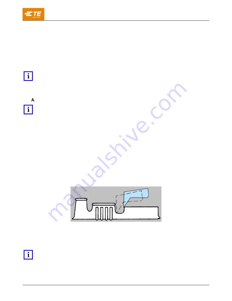
2. Watch the feed pawl as the machine is hand-cycled (or slowly cycled) several times. It should have
enough over-travel on the backstroke to pick up the next terminal, but not so much over-travel that the
feed pawl moves up onto the body of the terminal (see Figure 16).
If the pick-up point is the mating end of the terminal, the backstroke over-travel should be about
equal to the distance between the wire barrel and the mating end of the terminal (Figure 2).
For other types of terminals (for example, ring tongue), over-travel should be about the same,
depending on the terminal features and configurations (for example, stud hole).
Figure 16: Feed pawl backstroke over-travel
3. Check the backstroke position.
If the backstroke position is correct, the tab is correctly slugged out, and the terminals are not
damaged, the feed adjustments are complete.
If not, continue to the next step.
NOTE
Two adjustments work in combination to properly position the lead terminal over the anvil and give the proper backstroke
position to pick up the next terminal feed hole. Use
one
or
both
adjustment types to properly adjust the applicator.


