background image


Page 14 / 101                                   ECOC: EGC0 ; LOC: AI 

528050-1 


412-18876  Rev. G 


Inbetriebnahme  


8.1 

Anschließen an das Druckluftnetz 


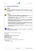
GEFAHR! 
 
Es  besteht  die  Restgefahr  des  Quetschens  von  Fingern.  Versuchen  Sie  nie,  in  die 
Gefahrenstelle zu greifen.


WARNUNG! 


Die Crimpmaschine darf ausschließlich mit montiertem Gesenkadapter und 

Gesenkpaar betrieben werden. 


Die Crimpmaschine darf nur in einem vollständigen und funktionsfähigen Zustand 

betrieben werden. 


Tragen Sie beim Arbeiten mit der Pneum. Parallel Crimpmaschine AT-SC


keine lose 

Kleidung,  losen  Schmuck  oder  lange,  offene  Haare,  welche  sich  in  den  Teilen  der 
Pneum. Parallel Crimpmaschine AT-SC verfangen können.  


Arbeiten Sie sorgfältig. 


Bei  Feststellung  von  Mängeln  an  der  Maschine  muss  die  Arbeit  unterbrochen  und 

die Störung behoben werden, bevor es weiter mit der Maschine gearbeitet wird. 


Es darf nur eine Person an oder mit der Maschine tätig sein.  


Es darf nur geschultes Personal an der Maschine tätig werden. 


Es darf nur mit dem angegebenen Betriebsdruck gearbeitet werden.


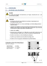
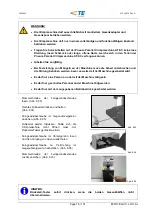
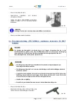
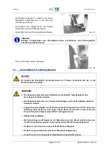
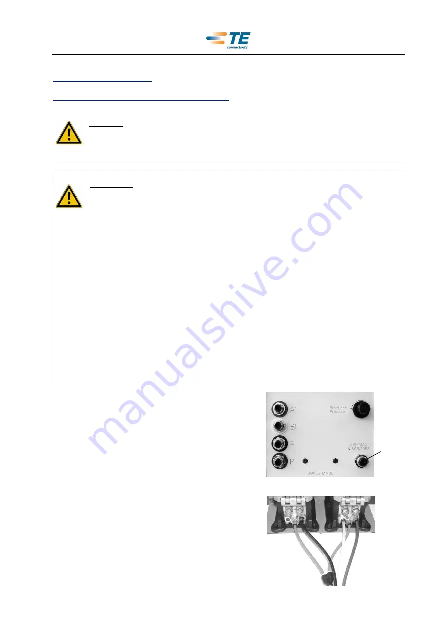
Vierfachschlauch  gemäß  Farbcodierung  hinten  an 
der Maschine (Abb. 8.01)  und  am Doppelfußpedal 
(Abb. 8.02) anschließen. 


Grüner Schlauch   

→  A1  Grün 


Weißer Schlauch   

→  B1  Weiß 


Schwarzer Schlauch 

→  A    Schwarz 


Blauer Schlauch 


→  P    Blau 


Abb. 8.01 

Abb. 8.02 


Содержание AT-SC

Страница 1: ...ebsanleitung Pneum Parallel Crimpmaschine AT SC P N 528050 1 412 18876 5 744013 6 30 06 2016 Rev G Operating Instructions Pneum Parallel Crimp Machine AT SC P N 528050 1 Mode d Emploi Machine Pneum Se...

Страница 2: ...76 Rev G Deutsche Version Inhaltsverzeichnis 3 English Version Table of contents 36 Version Fran aise Table des mati res 69 Vertrieb Sale Vente Tyco Electronics AMP GmbH a TE Connectivity Ltd Company...

Страница 3: ...hnische Beschreibung 11 6 1 Funktions und Bedienungselemente 11 6 2 Technische Daten 12 6 3 R ckstell Taster 12 7 Transport und Aufstellung 12 7 1 Transport 12 7 2 Aufstellung 13 8 Inbetriebnahme 14 8...

Страница 4: ...ung 26 17 Ersatzteilliste Pneumatikschema Elektroschema 27 17 1 Explosionszeichnung 27 17 2 St ckliste Explosionszeichnung 28 17 3 Pneumatik Schema 32 17 4 St ckliste Pneumatik Schema 33 17 5 Pneumati...

Страница 5: ...zum Umweltschutz zu erg nzen Rechtsverbindlich ist die deutsche Originalfassung Die Bedienungsanleitung ist f r sp tere Verwendung aufzubewahren 1 2 Sicherheitshinweise in der Betriebsanleitung Auf di...

Страница 6: ...Fachleuten vorbehalten Eigenm chtige Ver nderungen an der Maschine schlie en eine Haftung des Herstellers bzw Lieferers f r daraus resultierende Sch den aus 2 2 Hinweise zum Einrichten und Betreiben d...

Страница 7: ...eum Parallel Crimpmaschine AT SC ist nur mit schriftlicher Zustimmung des Herstellers zul ssig Jede nicht bewilligte Einsatzart der Pneum Parallel Crimpmaschine AT SC gilt als nicht bestimmungsgem F r...

Страница 8: ...r Maschine befasst anhand der vorliegenden Betriebsanleitung genauestens instruiert worden ist Der Betreiber der Pneum Parallel Crimpmaschine AT SC tr gt ferner die Verantwortung f r die Ausbildung de...

Страница 9: ...rbeit an der Crimpmaschine O Trennen Sie die Pneum Parallel Crimpmaschine AT SC vom Druckluftnetz bevor Sie irgendwelche Wartungs und Demontagearbeiten vornehmen Es besteht die Restgefahr des Quetsche...

Страница 10: ...g L nge 560 mm Breite 350 mm H he 505 mm Gesamtgewicht 32 kg GEFAHR F r den Transport muss ein ausreichend dimensioniertes Hebezeug verwendet werden 5 2 Lieferumfang 1 Stk Pneum Parallel Crimpmaschine...

Страница 11: ...be 03 Schmiernippel 04 Obere Gesenkaufnahme 05 Untere Gesenkaufnahme 06 Klemmschraube H he 07 Klemmschraube Schaft 08 Gesenkadapter 09 Gesenkeinsatz 10 R ckstell Taster 11 St ckz hler 12 Manometer 13...

Страница 12: ...kabelschuhes blockiert wird die Pneum Parallel Crimpmaschine AT SC wie folgt gel st Trennen Sie die Maschine vom Druckluftnetz Bet tigen Sie den R ckstell Taster 7 Transport und Aufstellung 7 1 Transp...

Страница 13: ...Allgemeinen muss der Wartungswert der Beleuchtungsst rke mindestens 500 lx betragen Stellen Sie das Doppelfu pedal auf den Fu boden Jede andere Platzierung des Doppelfu pedals als auf dem Fu boden ist...

Страница 14: ...osen Schmuck oder lange offene Haare welche sich in den Teilen der Pneum Parallel Crimpmaschine AT SC verfangen k nnen Arbeiten Sie sorgf ltig Bei Feststellung von M ngeln an der Maschine muss die Arb...

Страница 15: ...ftschlauch Schlauchl nge 1 Meter anschlie en Die Maschine ist nur durch die Hauptluftzuleitung komplett drucklos zu machen Abb 8 01 Pos 1 HINWEIS Nur aufbereitete und gereinigte Druckluft verwenden 8...

Страница 16: ...Maschine gearbeitet wird Es darf nur eine Person an oder mit der Maschine t tig sein Es darf nur geschultes Personal an der Maschine t tig werden Es darf nur mit dem angegebenen Betriebsdruck gearbei...

Страница 17: ...maschine darf nur in einem vollst ndigen und funktionsf higen Zustand betrieben werden Tragen Sie beim Arbeiten mit der Pneum Parallel Crimpmaschine AT SC keine lose Kleidung losen Schmuck oder lange...

Страница 18: ...Sie die pneumatische Versorgung bevor Sie den Gesenkadapter bzw die Gesenke auswechseln WARNUNG Die Crimpmaschine darf ausschlie lich mit montiertem Gesenkadapter und Gesenkpaar betrieben werden Die...

Страница 19: ...Versorgung getrennt wurde Unterbrechen Sie die pneumatische Versorgung bevor Sie den Gesenkadapter bzw die Gesenke auswechseln WARNUNG Die Crimpmaschine darf ausschlie lich mit montiertem Gesenkadapte...

Страница 20: ...NG Die Crimpmaschine darf ausschlie lich mit montiertem Gesenkadapter und Gesenkpaar betrieben werden Die Crimpmaschine darf nur in einem vollst ndigen und funktionsf higen Zustand betrieben werden Tr...

Страница 21: ...ndere f r das Doppelfu pedal und den R ckstell Taster Verlegen Sie die Schl uche am Boden so dass sie keine Stolpergefahr bilden 10 1 Bedienung des Doppelfu pedals Das linke Fu pedal ffnet und schlie...

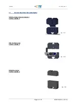
Страница 22: ...GC0 LOC AI 528050 1 412 18876 Rev G 11 Auswechselbare Gesenkadapter SDE Die Holder Standardadapter TE P N 1 528051 0 PEZ 100 Die Holder TE P N 1 528051 2 ERGO Die Holder TE P N 1 528051 6 Abb 11 01 Ab...

Страница 23: ...arallel Crimpmaschine AT SC verfangen k nnen Die Crimpmaschine darf nur in einem vollst ndigen und funktionsf higen Zustand betrieben werden Die Crimpmaschine darf ausschlie lich mit montiertem Gesenk...

Страница 24: ...der hinteren Zylinderaufnahme len aller beweglichen Hebel und Bolzen Durchf hrung Pneum Anschluss trennen Geh useabdeckung entfernen Schmieren der hinteren Zylinderaufnahme mit Blaser Swiss Lube Art...

Страница 25: ...ungen d rfen nur von fachkundigem Personal entfernt werden Tragen Sie beim Arbeiten mit der Pneum Parallel Crimpmaschine AT SC keine lose Kleidung losen Schmuck oder lange offene Haare welche sich in...

Страница 26: ...eiten d rfen nur von berechtigten und f r diese T tigkeit ausgebildeten Personen ausgef hrt werden Gesenkadapter und Gesenke d rfen nur bei Stillstand und ausgeschalteter Maschine entfernt werden Insb...

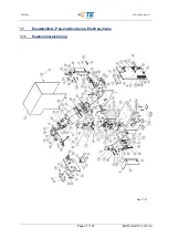
Страница 27: ...Page 27 101 ECOC EGC0 LOC AI 528050 1 412 18876 Rev G 17 Ersatzteilliste Pneumatikschema Elektroschema 17 1 Explosionszeichnung Abb 17 01...

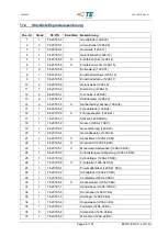
Страница 28: ...6 02 16 1 6 523795 3 X F hrungszapfen 1296 27 17 1 1 523781 3 St ssel 1296 09 BA 18 1 1 523781 2 Nocken 1296 21 SSC 19 1 2 523796 7 Gesenkf hrung 1296 23 20 1 6 523795 4 Gewindezapfen 1296 24 21 1 6 5...

Страница 29: ...523795 5 X Linsenschraube mit Iskt M3x25 54 12 8 523795 6 X Linsenschraube mit Iskt M4x10 55 10 519004 1 X Senkschraube mit Iskt M3x6 DIN7991 56 4 3 519004 1 X Senkschraube mit Iskt M6x20 DIN7991 57 2...

Страница 30: ...be mit Ms Bolzen 90 1 5 519000 2 Zylinderschraube mit Iskt DIN 912 M8x10 91 1 2 523781 4 X 5 2 Wegeventil K52DP218 92 1 9 523795 7 Zylinderr 93 2 3 519000 8 Zylinderschraube mit Iskt DIN 912 M5x45 94...

Страница 31: ...3796 0 X Kugel 3 0mm 119 1 3 519011 5 X Gewindestift mit Iskt M5x5 DIN913 120 1 1 523781 5 Klemmschraube oben 1296 30 Alle Ersatzteile die nicht mit einem X gekennzeichnet sind sind oder stehen in Ver...

Страница 32: ...Page 32 101 ECOC EGC0 LOC AI 528050 1 412 18876 Rev G 17 3 Pneumatik Schema Abb 17 02...

Страница 33: ...Anschluss Gerade F4PB8 1 8 25 1 3 523796 0 X Anschlusswinkel C64PMK6 1 8 26 2 6 523791 3 X Anschlusswinkel C64PMK4 1 8 27 1 1 523796 6 X Anschlusswinkel C63SPK8 1 4 28 2 2 523796 8 X Anschlusswinkel C...

Страница 34: ...ntage sollte durch TE erfolgen Beim Austausch von sicherheitsrelevanten Bauteilen oder Teilen die mit diesen in Verbindung stehen durch den Endanwender erlischt jeglicher Garantie und oder Gew hrleist...

Страница 35: ...ECOC EGC0 LOC AI 528050 1 412 18876 Rev G 17 6 Elektro Schema 18 Konformit tserkl rung Die Konformit tserkl rung wurde im Original zusammen mit dem Lieferschein und der Rechnung der Maschine versende...

Страница 36: ...Operators Guide 44 6 2 Technical Data 45 6 3 Release Button 45 7 Transport and Installation 45 7 1 Transport 45 7 2 Installation 46 8 Comissioning 47 8 1 Connecting to Compressed Air Supply 47 8 2 Mac...

Страница 37: ...ed View Drawing Spare Part List Pneumati and Electric Diagramm 60 17 1 Exploded View Drawing 60 17 2 Parts List Exploded View Drawing 61 17 3 Pneumatic Diagram 65 17 4 Parts List Pneumatic 66 17 5 Pne...

Страница 38: ...ational regulations for accident prevention and protection of the environment The German original version is legally binding This operating manual has to be guarded for later use 1 2 Warning Safety Pr...

Страница 39: ...is responsible for work on the pneumatic equipment Such work should only be carried out by specially trained staff Should the user make any changes to the machine without consulting the manufacturers...

Страница 40: ...op unit With the Pneum Parallel Crimp Machine AT SC the most common terminals on the market can be crimped with the TE interchangeable crimping systems All other applications of the Pneum Parallel Cri...

Страница 41: ...the machine have been thoroughly trained on the system using the this instruction manual The user is also responsible for the training of operators and the instruction must include the following aspec...

Страница 42: ...Crimp Machine AT SC from the air supply before attempting any maintenance work Due to the risk of hand or finger injury never try to reach into the machine before having assured that the machine is di...

Страница 43: ...or storage Dimension Length 560 mm Width 350 mm Height 505 mm Gross Weight 32 kg DANGER Use a chain hoist for the transport of the crimping machine 5 2 Packing Contents 1 pc Pneum Parallel Crimp Machi...

Страница 44: ...e 04 Upper Holder for Die Adapter 05 Lower Holder for Die Adapter 06 Locking Screw Height 07 Locking Screw Shaft 08 Adapter for Dies 09 Crimping Die 10 Release Button 11 Counter 12 Air Gauge 13 Compre...

Страница 45: ...handling errors or wrongly placed terminals the jaws can be opened as follows Disconnect the machine from the air supply Press Release Button 7 Transport and Installation 7 1 Transport The weight of t...

Страница 46: ...iate illumination of the working place EN 1837 1999 chapter 4 2 The general value of illumination has to be 500 lx Place the double foot petal on the floor No other place is allowed INFORMATION When t...

Страница 47: ...ing jewellery or long loose hair that can get caught in the Pneum Parallel Crimp Machine AT SC Work with caution In cases of a machine malfunction production must be stopped and the malfunction must b...

Страница 48: ...pressed air supply with supplied compressed air tube length 1m The machine can only be depressurized by disconnecting the machine from the main air supply Fig 8 01 Pos 1 INFORMATION Use only lubricate...

Страница 49: ...e person is allowed to work on or with the machine Only trained personal are allowed to work on or with the machine It is only allowed to work with the specified working pressure Loosen set screw of t...

Страница 50: ...only allowed to be used when it is in complete functional condition When working with the Pneum Parallel Crimp Machine AT SC do not wear loose clothing jewellery or long loose hair that can get caugh...

Страница 51: ...connected from the air supply Disconnect the air supply before changing the adapter or the dies CAUTION The crimp machine is only allowed to be used with mounted adapter and die set The crimp machine...

Страница 52: ...e is disconnected from the air supply Disconnect the air supply before changing the adapter or the dies CAUTION The crimp machine is only allowed to be used with mounted adapter and die set The crimp...

Страница 53: ...dangerous area CAUTION The crimp machine is only allowed to be used with mounted adapter and die set The crimp machine is only allowed to be used when it is in complete functional condition When work...

Страница 54: ...e main control switch Place the tubes and cables on the floor so that they do not cause a trip hazard 10 1 Operation of the Double Foot Pedal The left foot pedal opens and closes the upper die holder...

Страница 55: ...GC0 LOC AI 528050 1 412 18876 Rev G 11 Interchangeable Die Adapters SDE Die Holder Standard Adapter TE P N 1 528051 0 PEZ 100 Die Holder TE P N 1 528051 2 ERGO Die Holder TE P N 1 528051 6 Fig 11 01 F...

Страница 56: ...t caught in the Pneum Parallel Crimp Machine AT SC The crimp machine is only allowed to be used when it is in complete functional condition The crimp machine is only allowed to be used with mounted ad...

Страница 57: ...o 00492 01 EP Universal Grease 1 Shock pressure Greasing the rear cylinder mounting flange lubricating all moving parts Procedure Disconnect pneumatic supply Remove housing Grease the rear cylinder mo...

Страница 58: ...d the covers in particular may only be removed by specially trained personnel When working with the Pneum Parallel Crimp Machine AT SC do not wear loose clothing jewellery or long loose hair that can...

Страница 59: ...only by authorized and properly trained personnel Die adapter and dies may only be removed when the machine is not in operation and has been disconnected from the air supply The housing and the cover...

Страница 60: ...Page 60 101 ECOC EGC0 LOC AI 528050 1 412 18876 Rev G 17 Exploded View Drawing Spare Part List Pneumati and Electric Diagramm 17 1 Exploded View Drawing Fig 17 01...

Страница 61: ...16 1 6 523795 3 X Guide Pin 1296 27 17 1 1 523781 3 Pusher 1296 09 BA 18 1 1 523781 2 Tappet 1296 21 SSC 19 1 2 523796 7 Die Guidance 1296 23 20 1 6 523795 4 Threaded Pin 1296 24 21 1 6 523795 5 X Cov...

Страница 62: ...ns Head Screw M3x25 54 12 8 523795 6 X Hex Lens Head Screw M4x10 55 10 519004 1 X Hex Socket Countersunk Head Screw M3x6 DIN7991 56 4 3 519004 1 X Hex Socket Countersunk Head Screw M6x20 DIN7991 57 2...

Страница 63: ...X Jackscrew with brass pin 90 1 5 519000 2 Hex Socket screw DIN 912 M8x10 91 1 2 523781 4 X 5 2 Pneum Valve K52DP218 92 1 9 523795 7 Cylinder 93 2 3 519000 8 Hex Socket screw DIN 912 M5x45 94 1 3 519...

Страница 64: ...DIN915 118 1 1 523796 0 X Ball 3 0mm 119 1 3 519011 5 X Hex Socket Set Screw M5x5 DIN913 120 1 1 523781 5 Upper Clamp Screw 1296 30 All spare parts which are not marked with an X are safety related pa...

Страница 65: ...Page 65 101 ECOC EGC0 LOC AI 528050 1 412 18876 Rev G 17 3 Pneumatic Diagram Fig 17 02...

Страница 66: ...0 X Hose Nipple F4PB8 1 8 25 1 3 523796 0 X Angle Hose Stem C64PMK6 1 8 26 2 6 523791 3 X Angle Hose Stem C64PMK4 1 8 27 1 1 523796 6 X Angle Hose Stem C63SPK8 1 4 28 2 2 523796 8 X Angle Hose Stem C6...

Страница 67: ...hine The assembly should be made from TE If the replacement of the safety related parts or parts which are in connection with these safety related parts is done by the end user every guarantee and war...

Страница 68: ...101 ECOC EGC0 LOC AI 528050 1 412 18876 Rev G 17 6 Electric Diagram 18 Declaration of Conformity The original declaration of conformity was supplied together with the delivery note of the machine Fig...

Страница 69: ...Technique 77 6 1 El ments de Fonction et d Utilisation 77 6 2 Donn es Techniques 78 6 3 L Interrupteur d Arr t 78 7 Transport et Mise en Place 78 7 1 Transport 78 7 2 Mise en Place 79 8 Mise en Servic...

Страница 70: ...Diagramme et Liste des Pi ces D tach es Sch ma Pneumat et Electr 93 17 1 Diagramme des Pi ces D tach es 93 17 2 Liste des P eces D tach es 94 17 3 Sch ma Pneumatique 98 17 4 Liste des Pi ces D tach es...

Страница 71: ...t de l environnement Seule la version originale allemande est juridiquement valable Le mode d emploi est conserver pour les utilisations futures 1 2 Indications Relatives la S curit figurant dans le M...

Страница 72: ...omp tence pour les travaux sur l quipement pneumatique en particulier doit tre clairement d finie Ce genre de travail est r serv des sp cialistes Les transformations en propre r gie de la machine excl...

Страница 73: ...mme machine table La Machine Pneum Sertir Parall le AT SC est pr vu pour la sertissage de la plupart des cosses sertir avec le syst me sertir interchangeable TE Pour toutes autres utilisations de la M...

Страница 74: ...ou de l entretien du machine connaisse avec pr cision le contenu du mode d emploi accompagnant la machine Il est en outre responsable de la formation du personnel de service qui doit couvrir les point...

Страница 75: ...effectuer toute op ration de maintenance Il existe un risque r siduel d crasement des doigts N essayez jamais de toucher l outil sans vous assurer que la machine est d branch e du r seau pneumatique O...

Страница 76: ...mm Hauteur 505 mm Poids total 32 kg DANGER Un appareil de levage de taille suffisante doit tre utilis pour le transport de la machine 5 2 Livraison Machine 1 pc Machine Pneum Sertir Parall le AT SC av...

Страница 77: ...teur d adaptateur sup rieur 05 Porteur d adaptateur inf rieur 06 Vis de serrage Hauteur 07 Vis de serrage Tige 08 Adaptateur pour matrices 09 Matrice sertir 10 L interrupteur d arr t 11 Compteur 12 Ma...

Страница 78: ...le l interrupteur d arr t et les m choires s ouvre Coupez l alimentation d air comprim Appuyez l interrupteur d arr t 7 Transport et Mise en Place 7 1 Transport Le poids total de la Machine Pneum Sert...

Страница 79: ...e la valeur d clairement pr conis e est de minimum 500 lx Posez la p dale double pied sur le sol Tout positionnement de la p dale double pied autre que sur le sol est interdit INFORMATION Si l utilisa...

Страница 80: ...ni pendentifs ni cheveux d tach s qui risqueraient d tre happ s par les pi ces de la machine Travaillez avec pr caution En cas de dysfonctionnements il faut arr ter de travailler sur la machine soluti...

Страница 81: ...e livr longueur 1m La d compression de la machine intervient uniquement par d branchement du tuyau pneumatique principal Fig 8 01 Pos 1 INFORMATION Utilisez seulement de l air comprim purifi et propre...

Страница 82: ...ailler sur ou avec la machine Seul un personnel form est autoris travailler sur la machine L utilisation de la machine n est autoris e qu avec la pression air comprim prescrite D visser la vis de serr...

Страница 83: ...ERTISSEMENT La machine sertir ne doit tre mise en service qu avec adaptateur et matrices mont s La machine sertir ne doit tre mise en service qu en parfait tat de marche Lors de travaux avec la Machin...

Страница 84: ...seau pneumatique D branchez la machine du r seau pneumatique avant de changer l adaptateur ou des matrices AVERTISSEMENT La machine sertir ne doit tre mise en service qu avec adaptateur et matrices m...

Страница 85: ...que la machine est d branch e du r seau pneumatique D branchez la machine du r seau pneumatique avant de changer l adaptateur ou des matrices AVERTISSEMENT La machine sertir ne doit tre mise en servi...

Страница 86: ...one dangereuse AVERTISSEMENT La machine sertir ne doit tre mise en service qu avec adaptateur et matrices mont s La machine sertir ne doit tre mise en service qu en parfait tat de marche Lors de trava...

Страница 87: ...ur la p dale double pied l interrupteur d arr t et l interrupteur principal D placez les tuyaux sur le sol de telle fa on emp cher tout risque de tr bucher 10 1 Maniement de la P dale Double Pied La p...

Страница 88: ...C AI 528050 1 412 18876 Rev G 11 Adaptateurs Matrices Interchangeables SDE Die Holder Adaptateur Standard TE P N 1 528051 0 PEZ 100 Die Holder TE P N 1 528051 2 ERGO Die Holder TE P N 1 528051 6 Fig 1...

Страница 89: ...happ s par les pi ces de la machine La machine sertir ne doit tre mise en service qu en parfait tat de marche La machine sertir ne doit tre mise en service qu avec adaptateur et matrices mont s Trava...

Страница 90: ...s Lube Art No 00492 01 EP Univ Graisse 1 Pression Graisser le support des cylindres L arri re et Huiler les leviers et les axes articul Ex cution Interrompez l air comprim Enlevez la couverture Graiss...

Страница 91: ...articulier ne doivent tre enlev s que par un personnel qualifi Lors de travaux avec la Machine Pneum Sertir Parall le AT SC ne porter ni v tements amples ni pendentifs ni cheveux d tach s qui risquera...

Страница 92: ...Les op rations de r paration ne doivent tre effectu es que par le personnel autoris et form cette activit L adaptateur et les matrices ne doivent tre enlev s qu l arr t de la machine Les carters et le...

Страница 93: ...Page 93 101 ECOC EGC0 LOC AI 528050 1 412 18876 Rev G 17 Diagramme et Liste des Pi ces D tach es Sch ma Pneumat et Electr 17 1 Diagramme des Pi ces D tach es Fig 17 01...

Страница 94: ...1296 02 16 1 6 523795 3 X Pivot de guidage 1296 27 17 1 1 523781 3 Pilon 1296 09 BA 18 1 1 523781 2 Came 1296 21 SSC 19 1 2 523796 7 Guidage des Matrices 1296 23 20 1 6 523795 4 Bouchon filet e 1296 2...

Страница 95: ...4x14 53 2 8 523795 5 X Vis avec 6 p M3x25 54 12 8 523795 6 X Vis avec 6 p M4x10 55 10 519004 1 X Vis Noy e avec 6 p M3x6 DIN7991 56 4 3 519004 1 X Vis Noy e avec 6 p M6x20 DIN7991 57 2 519021 7 X Ecro...

Страница 96: ...pression avec laiton gouchon 90 1 5 519000 2 Vis t te cyl avec 6 p creux DIN 912 M8x10 91 1 2 523781 4 X 5 2 Vanne pneum K52DP218 92 1 9 523795 7 Cylindre 93 2 3 519000 8 Vis t te cyl avec 6 p creux...

Страница 97: ...e avec 6 p M3x6 DIN915 118 1 1 523796 0 X Boule 3 0mm 119 1 3 519011 5 X Tige Filet e avec 6 p M5x5 DIN913 120 1 1 523781 5 Vis de Blocage sup rieur 1296 30 Toutes les pi ces de rechange qui ne sont p...

Страница 98: ...Page 98 101 ECOC EGC0 LOC AI 528050 1 412 18876 Rev G 17 3 Sch ma Pneumatique Fig 17 02...

Страница 99: ...X Equerre m le C64SPK8 1 8 24 1 6 523791 0 X Raccord droite F4PB8 1 8 25 1 3 523796 0 X Equerre m le C64PMK6 1 8 26 2 6 523791 3 X Equerre m le C64PM K4 1 8 27 1 1 523796 6 X Equerre m le C63SPK8 1 4...

Страница 100: ...onnect s avec tels l ments L assemblage devrais tre ex cut par TE Dans l change par l utilisateur final des l ments important pour la s curit ou des l ments qui sont connect s avec tels la garantie et...

Страница 101: ...e 101 101 ECOC EGC0 LOC AI 528050 1 412 18876 Rev G 17 6 Sch ma Electrique 18 D claration de Conformit L original de la d claration de conformit tait livr avec le bon de livraison de la machine Fig 17...

Отзывы: